- 12 -
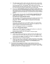
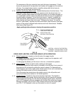
c) Pull cable upward (pull the cable to the right when facing the control plate
on 15 & 17 HP Kawasaki units) until alignment holes in control plate lever
and control plate line up. For Kawasaki 15/64” (6mm) drill bit can be
inserted through these two holes to align them. For Kohler use a 19/64” drill
bit. Once the holes are aligned, tighten clamp onto throttle cable.
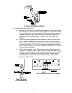
d) Be sure the
choke adjusting screw just contacts the choke lever
when
the throttle control is in the full throttle position. Choke link should not move
when throttle control is moved to the full throttle position. Choke must be
completely closed when throttle lever is moved to the full forward “CHOKE”
position.
e) This step needs to be done after the
unit has been assembled and the
engine has been started
. Refer to Section 4. (Operation Instructions).
For Kohler and 14 HP Kawasaki engines
:
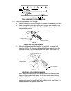
Check the engine “STOP” position by moving the throttle control fully to the
rear. (Note: There is a detent toward the lower end of the slot in the
console for “IDLE”; the “STOP” position is rearward from this detent).
For Kohler engines
:
If the engine continues to run in the "STOP" position, turn the kill switch
adjusting screw inward until engine stops, then give it an additional 1/2 to
3/4 turn to assure it will always function properly.
(The 14 HP Kawasaki kill switch is not adjustable)
.
For 15 & 17 HP Kawasaki engines
:
There is not a “STOP” position. The engine will continue to run when the
throttle control is moved past the rear detent.
Turn the ignition switch to the “off” position to stop the engine.
For B&S Vanguard Engines:
a) Position the throttle control lever (on console) 1/8" from the upper end of
the slot. Route the throttle cable along the right side of the upper handle,
under the fuel tank support, and position the cable on the
right
side of the
engine between the oil fill tube and engine.
b) Attach the inner wire to the appropriate throttle control lever on the engine.
Loosen the cable clamp on the engine, place the cable behind it and pullup
on the cable to move the throttle linkage to the
full
throttle
position.
Tighten the cable clamp screw.
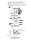
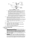
3.9 Connect the blade engagement linkages. Loosen jamnut and remove
turnbuckle from lower linkage. Screw turnbuckle onto both upper and lower
linkages simultaneously. (See figure 5) Note that the threads on upper linkage
are left hand. See 5.2.2 for linkage adjustment.


