


- 28 -
clearance to ground.
Do
Not
adjust rollers to support the deck. Be sure
roller bolts and nuts are installed with the spring disc washer between
head of bolt and mounting bracket.
Torque to 40-45 ft-lbs., or loss of
roller may result
.
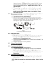
c) When operating in extremely rough conditions it may be necessary to
position the anti-scalp rollers one or two holes higher than described in
"b" to prevent damage to the rollers and/or bolt failure(See Figure 14).
NOTE:
When anti-scalp rollers are placed in these positions, reduced
deck flotation will result.
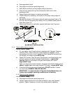
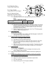
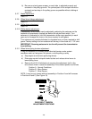
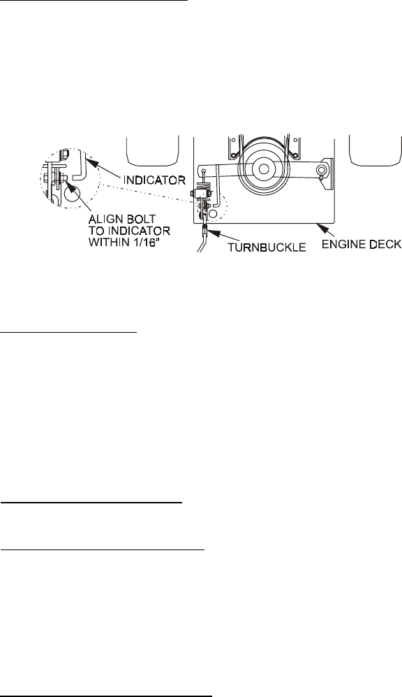
5.2.2 Blade engagement Linkage: Located between the blade engagement lever on
the left handle and the left rear corner of the engine deck.
a) Stop engine and remove spark plug wire(s).
b) With blade drive engaged, adjust the linkage length by loosening the
locknut on the turnbuckle and adjusting the turnbuckle so that the bolt on
the bellcrank and the indicator arm align with each other within 1/16”.
See Figure 15. Tighten locknut against turnbuckle.
FIG. 15
BLADE ENGAGEMENT LINKAGE
5.2.3 Blade Safety Switch:
a) Stop engine and remove spark plug wire(s).
b) With blades disengaged and the bellcrank touching the rear of the slot in
the engine deck, adjust the blade safety switch (if needed) until the
bellcrank arm is 5/16” from the switch body.
c) Be sure the bellcrank
DOES NOT
touch the switch body or damage to the
switch could occur.
d) Retighten blade switch mounting hardware.
5.2.4 Engine to Cutter Deck Belt:
No adjustment necessary
.
5.2.5 Transmission Belt Adjustment:
a) Stop engine and remove spark plug wire(s).
b) To tighten transmission belt, loosen the 3/8” nyloc nut on transmission
belt idler pulley. Slide bolt inward in slot and retighten nyloc nut.
c) When properly adjusted, the belt should have 1/2” of deflection with three
pounds of pressure on the belt midway between the transmission and
engine pulley.
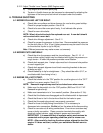
5.2.6 Wheel drive belts and scrapers:
a) If wheel traction appears to be slipping, drive lever rods may be touching
bottom of neutral lock/park brake latch slot. To adjust, refer to directions
in Section 3.11
NOTE: Wheel drive springs have three tension settings. Refer to Section
5.2.11.