


Maintenance
CAUTION
Raising the mower deck for service or
maintenance relying solely on mechanical
or hydraulic jacks could be dangerous. The
mechanical or hydraulic jacks may not be
enough support or may malfunction allowing
the unit to fall, which could cause injury.
Do Not rely solely on mechanical or hydraulic
jacks for support. Use adequate jack stands
or equivalent support.
5. Remove the rear tires from the machine.
6. Remove any debris from the brake area.
7. Engage the parking brake (lever up).
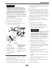
8. Loosen the jam nut (item 9 in Figure 22) just
above the trunnion roller 2-3 turns.
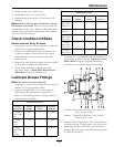
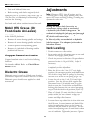
Figure 22
1. Lever down
(disengaged)
6. Remove pin to adjust
rod length for additional
brake adjustment
2. Lever up (engaged)
7. Trunnion roller
3. Nyloc nut below trunnion
roller
8. Spring retainer bracket
4. Nyloc nut below spring 9. Jam nut above trunnion
roller
5. 1/8 to 3/16 inch (3.2 to
4.8 mm)
9. Tighten the bottom nyloc nut (item 3 in Figure 22)
until the brake spring is completely compressed,
then loosen one-half turn.
10. Tighten the jam nut against the trunnion roller
11. Check the clearance between the bottom of the
brake bracket and the nyloc nut just under the
spring. Clearance should measure 1/8 to 3/16
inch (3.2-4.8 mm). If necessary, adjust the nyloc
nut accordingly.
12. If the correct gap can no longer be achieved
because there is no clearance between the nyloc
nut below the spring and the jam nut, or there
are no threads left in the bottom nyloc nut, the
length of the brake rod can be adjusted. Remove
a pin from a yoke at either end of the brake rod
and lengthen (or shorten) the brake rod until the
correct gap can be achieved.
13. If a brake component has been removed or
replaced, see the steps below; otherwise proceed
to step
14.
Burnishing the Brake Procedure:
A. Clear the area of any ammable material
before starting the burnishing process.
B. While sitting in the operator’s seat, start the
engine, and release the park brake.
WARNING
Engine must be running and drive wheels
must be turning so adjustments can be
performed. Contact with moving parts or
hot surfaces may cause personal injury.
Keep ngers, hands, and clothing clear of
rotating components and hot surfaces.
C. Increase the throttle to high idle.
D. Bring both drive levers out of neutral and
push them into full forward position.
E. Pull the park brake lever up until the engine
rpm starts to drop. Hold the park brake lever
in this position for 15 seconds.
F. Release the brake lever.
G. Move the drive levers into the full reverse
position. Repeat steps E and F.
H. Move the drive levers back to the neutral lock
position.
I. Return the throttle to low idle, and stop the
engine.
J. Allow the brake bands and drums to cool.
Repeat steps
7 through 11.
14. Install the tires and torque the lug nuts to 90-95
ft-lb (122-129 N-m).
15. Remove the jack stands.
43