


Maintenance
Leveling) lower than the rear blade tip, adjust the
blade level using the following instructions:
2. Park the machine on a level surface and disengage
the blade control switch.
3. Move the motion control levers outward to
the neutral position, engage the parking brake,
stop the engine, remove the key, and wait for all
moving parts to stop before leaving the operating
position.
4. Check the air pressure of all four tires. If needed,
adjust to the recommended ination; refer to
Checking the Tire Pressure in Drive System
Maintenance section.
5. Check and adjust the side-to-side blade level if
you have not checked the setting; refer to Deck
Leveling.
6. Set the height-of-cut lever to the 3 inch (76 mm)
position. Place two “B” thick blocks (see Block
Height and Rake Table in Deck Leveling) under
the rear edge of the cutting deck skirt; one on
each side of the cutting deck. Place two “A” thick
blocks (see Block Height and Rake Table in Deck
Leveling) under each side of the front edge of the
deck, but not under the anti-scalp roller brackets.
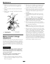
7. Loosen the leveling adjust locking nuts (item 1
Figure 24) on all four corners so that the deck is
sitting securely on all four blocks. Make sure that
the slack is removed from the deck hangers and
the deck lift foot lever is pushed back against the
stop, then tighten the four leveling adjust locking
nuts.
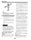
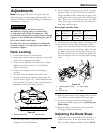
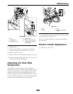
8. Carefully rotate the blades so they are facing front
to rear (
Figure 25).
9. Measure from the tip of the front blade to the at
surface and the tip of the rear blade to the at
surface (Figure 25). If the front blade tip is not
“R” (see Block Height and Rake Table in Deck
Leveling) lower than the rear blade tip, adjust the
front deck hanger.
Figure 25
1. Blades front to rear
2. Measure here
10. When the front-to-rear blade slope is correct
check the side-to-side level of the mower again;
refer to Deck Leveling.
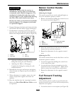
Pump Drive Belt Tension
Self-tensioning - No adjustment necessary.
Deck Belt Tension
Self-tensioning - No adjustment necessary.
Adjusting the Parking Brake
Service Interval: Every 500 hours
Check to make sure brake is adjusted properly. This
procedure must be followed after the rst 100 hours
or when a brake component has been removed or
replaced.
1. Drive the machine onto a level surface.
2. Disengage the blade control switch (PTO), move
the motion control levers to the neutral locked
position and set the parking brake.
3. Stop the engine, wait for all moving parts to stop,
and remove the key.
4. Setup the machine to be pushed by hand (see
Drive Wheel Release Valves in the Operation
section).
5. Raise the back of the machine up and support the
machine with jack stands.
36