


Operation
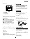
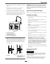
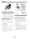
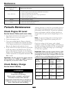
Figure 16
1. Deck lift foot pedal 3. Height of cut decal
2. Height adjustment pin 4. Transport lock control
5. Insert the height adjustment pin into the hole
corresponding to the desired cutting height.
See the decal on the side of the deck lift plate for
cut heights.
6. Push the deck lift pedal, release the transport lock
and allow the deck to lower to the cutting height.
Adjusting the Deck Lift Foot Pedal —
48 & 52 inch Decks Only
The deck lift foot pedal can be adjusted for operator
comfort.
1. Stop the machine and move the motion control
levers outward to the neutral locked position.
2. Disengage the PTO.
3. Engage the park brake.
4. Stop the engine, remove the key and wait for all
moving parts to stop.
5. Position the transport lock in the latching
position.
6. Raise and lock the deck to the 4 1/2 inch (11.4
cm) transport position (
Figure 16).
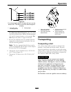
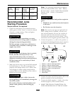
7. Remove the two nuts from the deck lift foot pedal
(see Figure 17).
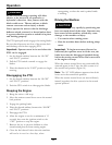
Figure 17
1. Deck lift foot pedal
4. Hole set that moves
the pedal closer to the
operator
2. Nuts 5. Hole set that moves the
pedal away from the
operator
3. Adjustment holes 6. Adjusts the pedal higher
or lower
8. Position the deck lift pedal for operator comfort
and reinstall the nuts. Tighten hardware.
Adjusting the Anti-Scalp Rollers
It is recommended to change the anti-scalp roller
position, when the height of cut has changed.
1. Stop the machine and move the motion control
levers outward to the neutral locked position.
2. Disengage the PTO.
3. Engage the park brake.
4. Stop the engine, remove the key and wait for all
moving parts to stop.
5. After adjusting the height of cut, adjust the
anti-scalp rollers by removing the nyloc nut,
bushing, spring disc washer and whizlock nut.
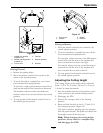
6. Place the rollers in one of the positions shown
(
Figure 18). Rollers will maintain 3/4 inch (19
mm) clearance to the ground to minimize gouging
and roller wear or damage.
26