


Maintenance
valves must be in the “released” position on the
hydros).
13. If the hub moves very freely relative to the caliper,
then tighten the standard nut one turn against the
swivel and repeat step 11.
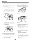
14. Once step 11 is achieved, hold the threaded rod
end with a tool and tighten the lock nut against
the standard nut. Do Not allow the cable to turn
when the nuts are tightened.
15. After adjusting the brakes on both sides of the
mower, cycle the brake handle a minimum of six
times to allow the cable to seat into the sheath
and mounting tabs.
16. Readjust both brakes following the procedure in
steps 10 through 14.
17. If a brake component has been removed or
replaced, see the steps below; otherwise proceed
to step 18.
Burnishing the Brake Procedure:
A. Clear the area of any ammable material
before starting the burnishing process.
B. Rotate the drive wheel release handle to the
“operating” position. Refer to the Drive
Wheel Release Valves section in Operation.
C. Apply the park brake.
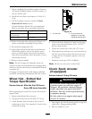
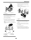
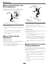
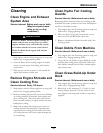
D. Install a 1/2 x 6 inch (approx.) rod or bolt
through the 2 inch height of cut hole (see
Figure 31).
Figure 31
1. 2 inch height of cut location
E. Start the mower while in the operator position.
WARNING
Engine must be running and drive wheels
must be turning so park brake adjustment
can be performed. Contact with moving
parts or hot surfaces may cause personal
injury.
Keep ngers, hands, and clothing clear of
rotating components and hot surfaces.
F. Release the park brake so the handle rests on
the 1/2 x 6 inch rod or bolt.
G. Move the throttle to high idle.
H. Move both motion control levers to the full
forward position and hold for 15 seconds.
I. Move both motion control levers to the full
reverse position and hold for 15 seconds.
J. Turn off the engine and completely release
the park brake by removing the 1/2 x 6 inch
rod or bolt.
K. Allow the hubs to cool until they are cool
enough to safely touch.
L. Rotate the drive wheel release handle to the
“released” position. Refer to the Drive Wheel
Release Valves section in Operation.
M. Readjust both brakes following the procedure
in steps 10 through 14.
18. Rotate the drive wheel release handle to the
“operating” position. Refer to the Drive Wheel
Release Valves section in Operation.
19. Install the rear tires and torque lug nuts to 90-95
ft-lb (122-129 N-m).
20. Remove jack stands.
Electric Clutch Adjustment
No adjustment necessary.
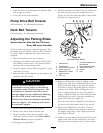
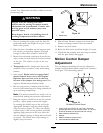
Motion Control Linkage
Adjustment
Located on either side of the fuel tank, below the seat
are the pump control linkages. Rotating the pump
linkage with a 1/2 inch wrench allows ne tuning
adjustments so that the machine does not move in
40