


97705C (Rev. J - 8/07)
EDFP217C*B EDFP217RAC EDFPVR217C EDFPVR217RAC
PAGE 6
INSTALLATION INSTRUCTIONS
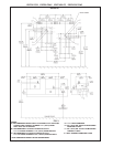
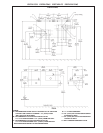
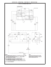
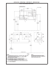
1. Wall should already be framed for the fountain using the positioning dimensions shown in Figures 3, 4,
5, or 6. Shown dimensions pertain to installation location (framing must support up to 300 lbs. weight).
These dimensions are required for compliance with ANSI Standard A117.0.
2. Install rough-in plumbing as shown in Figures 3, 4, 5, or 6. Waste line should extend a minimum of 2"
(51mm) through the back panel. Run the supply water inlet line through the back panel. Install a service
stop (not provided). Turn on supply water and flush thoroughly.
3. Install back panel.
EDFP217C: Place the upper edge of the panel above hanger bracket.
EDFP217C W/MOUNTING PLATE: Place the upper edge of the panel above mounting plate on the wall.
Slide the panel down until it engages the mounting plate. Be sure back panel is firmly engaged before
releasing it.
3. Remove bottom access panel from fountain basin and save the screws.
EDFP217C: Install the fountain to the back panel and wall using (4) 5/16" x 2" long lag bolts and washers
(not provided) through holes in back panel. Tighten securely.
EDFP217C W/WALL PLATE: Install the fountain to the back panel using (4) 5/16" x 3/4" long screws and
washers (provided) through holes in back panel. Tighten securely.
4. Remove elbow from end of p-trap and attach it to drain tube. Reattach elbow to p-trap and cut waste tube
to required length using plumbing hardware and trap as a guide.
5. Make water supply connections from service stop to the 3/8" O.D. unplated copper tube coming out of the
strainer. Turn on water supply and check for leaks. Newly installed water supply line should be insulated
after leak check is completed. DO NOT SOLDER TUBES INSERTED INTO THE STRAINER AS
DAMAGE TO THE O-RINGS MAY RESULT.
6. These products are designed to operate on 20-105 PSIG supply line pressure. If inlet pressure is above
105 PSIG, a pressure regulator must be installed in the supply line. Any damage caused by reason of
connecting these products to supply line pressures lower than 20 PSIG or higher than 105 PSIG is not
covered by warranty.
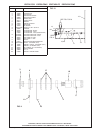
7. Check stream height from bubbler. Stream height is factory set at 35 PSI. If supply pressure varies
greatly from this, adjust the screw on regulator item 10 by using a small screwdriver through the small
hole in the push button item 3 (See Fig. 11). Clockwise adjustment will raise stream height and
counter-clockwise will lower stream height. For best adjustment stream should hit basin
approximately 6-1/2" (165mm) from bubbler.
8. Replace bottom access panel to fountain using the screws provided. Tighten securely.
TROUBLE SHOOTING AND MAINTENANCE
1. Orifice Assy: Mineral deposits on orifice can cause water flow to spurt or not regulate. Mineral deposits
may be removed from orifice with a small round file not over 1/8" diameter or a small diameter wire.
CAUTION: Do not file or cut orifice materials.
2. Stream Regulator: If orifice is free of material deposits, regulate flow according to instruction 7 stated
above.
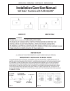
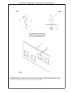
3. Actuation of Quick Connect Water Fittings: Cooler is provided with lead-free connectors which utilize
an o-ring water seal. To remove tubing from the fitting, relieve water pressure, push in on the gray collar
while pulling on the tubing (See Figure 2). To insert tubing, push tube straight into the fitting until it
reaches a positive stop, approximately 3/4".