


MAINTENANCE PERFORMED BY
AUTHORIZED SERVICE FACILITIES
Before working on the generator, ensure the fol-
lowing:
• The AUTO/OFF/MANUAL switch is in the OFF
position.
• The 15A fuse has been removed from the con-
trol box.
• The 120VAC supply to the battery charger is
switched OFF.
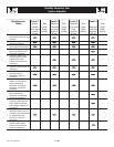
EVERY THREE MONTHS
1. Check battery condition.
2. Inspect and test fuel system.
3. Check transfer switch.
4. Inspect exhaust system.
5. Check engine ignition system.
6. Check fan belts.
ONCE EVERY SIX MONTHS
1. Test Engine Safety Devices (low oil pressure, low
coolant level, high coolant temperature).
ONCE ANNUALLY
1. Test engine governor; adjust or repair, if needed.
2. Clean, inspect generator.
3. Flush cooling system.
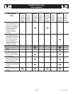
FIRST 100 OPERATING HOURS
1. Change engine oil and oil filter. After initial
change, service engine oil and filter at 150 operat-
ing hours or six months, whichever comes first.
2. Retorque cylinder head.
3. Retorque intake and exhaust manifold.
EVERY 500 OPERATING HOURS
1. Service air cleaner.
2. Check starter.
3. Check engine DC alternator.
EVERY 800 OPERATING HOURS
1. Retorque cylinder head.
2. Retorque intake and exhaust manifold.
3. Check engine compression.
4. Check valve clearance.
EXHAUST MANIFOLD PROCEDURE
1. If necessary, clean gasket surfaces on exhaust
manifold and cylinder head.
2. Install exhaust manifold and exhaust manifold
gasket.
3. Install fasteners.
NOTE:
Exhaust manifold fasteners must be tightened in
two stages.
4. Tighten fasteners to 20-30 N-m (15-22 lb-ft) dur-
ing the first stage.
5. Retighten fasteners to 60-80 N-m (44-59 lb-ft)
during the second stage.
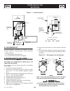
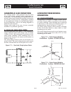
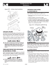
INTAKE MANIFOLD PROCEDURE
1. Clean and inspect the mounting surfaces of the
intake manifold and the cylinder head. Both sur-
faces must be clean and flat (Figure 10.1).
2. Clean and lightly oil the manifold bolt/stud
threads.
3. Install a new lower intake manifold gasket.
4. Position the lower intake manifold to the cylinder
head.
5. Install retaining bolts/studs finger tight.
6. Tighten all bolts/studs to specifications in the
tightening sequence shown:
• First pass = 7=10 N-m (5-7 lb-ft).
• Final pass = 26-38 N-m (19-28 lb-ft).
Figure 10.1 — Intake Manifold Installation
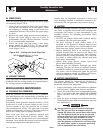
CYLINDER HEAD PROCEDURE
1. Position head gasket on the block (Figure 10.2).
2. Position cylinder head to cylinder block.
3. Install 10 cylinder head bolts in numerical
sequence. Tighten to 70 N-m (52 lb-ft) in sequence.
Retighten to 70 N-m (52 lb-ft) in sequence. Then
turn all head bolts an additional 90 - 100 degrees
in sequence.
10-1
Standby Generator Sets
Maintenance
Maint005 Rev. 0 08/05