6-ENGLISH
Never store the engine with fuel in the tank in a
poorly ventilated place where the fumes
produced by the gasoline could propagate and
reach a fire, candle, burner or furnace pilot light,
water heater, dryer, etc. Never store excessive
quantities of fuel.
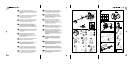
E1. Setting the motor on the frame
ƽ
Position the motor so that the fuel cap faces
upward and the bracket for fastening it to the
frame is on one side. Screw pin A onto the motor
as shown in the figure and tighten it securely.
Fasten the motor to the frame and tighten it
securely with the nut provided (B).
E2. Insertion of padding on frame
ƽ
Pick up the frame+motor assembly and place
them on the base; insert the upper part of the
padding on the frame and fasten it with the two
straps as shown in the figure. Take the support
for the starter knob and fit it as shown in the
figure. Fasten the starter cord to the support as
shown in figure.
E3. Assembly of the transmission shaft to the
flexible shaft
ƽ
Pull the plastic ring nut away from the end of the
rigid tube turning it counterclockwise if
necessary. Insert the rigid tube into the handle
section until the label is aligned with the edge of
the plastic threaded rim Tighten the ring nut
hand tight.
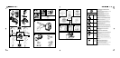
Safety pole guard
ƽ
The safety pole guard should be mounted using
the accessories supplied and in the configuration
shown in the figure,in contact with the delta
handle.
E4. Delta grip
ƽ
For your safety, fasten the delta handle in front
of the label placed on the shaft at a distance of
at least 11 cm from the rear grip. The handle
should be fastened in a comfortable working
position. If you are using sawtooth blades, the
grip distance should be moved by at least 36 cm.
E5. Fitting guard on line cutter head and
grass cutting blade
ƽ
Fit the safety guard (A) against the gearbox (I)
position the lower clamp (G) in the housing under
the shield and the upper clamp (F) over the shaft.
Insert and tighten the screws (H).
Safety guard extension (exclusively for use
with nylon string head)
ƽ
The extension (B) should be installed only for
use with the nylon string head, with the aid of the
string cutter blade (L), that regulates the length
of the string and thus the cutting diameter. For
correct assembly see the illustration on the cover
and perform the following sequence of steps:
Insert the extension (B) on the safety guard (A)
at the reference notches (C), and fasten with the
screws (D), then apply the string cutter blade (L)
with the cutting edge facing towards the outside
of the shield, and fasten it with the screw (E)
(Make sure the screws are tightened all the way
(E) and are not loosened by the vibrations. If
necessary, tighten them again).
E6. Assembly/disassembly of line cutter
head
ƽ
Apply the nylon string head as shown in the
illustration: a) Protection flange b) Upper plate c)
Nylon string head. Tighten by turning
counterclockwise. As you tighten, hold the nylon
string head and plate still and insert the wrench
or screwdriver supplied in the holes in the plate
and gearbox; first turn the plate until the two
holes match.
E7. Assembly/disassembly of grass cutter
blade
ƽ
Assemble blade as illustrated: a) Flange guard -
b) Upper cap with blade centering - c) Blade with
text and directional arrow facing upwards - d)
Lower washer - e) Fixed mower gauge - f) Blade
locking screw (length mm 16).
If you want to assemble the rotating mower
gauge,proceed as illustrated: a) Flange guard -
b) Upper cap with blade centering - c) Blade with
text and directional arrow facing upwards - d)
E. Assembly/disassembly
4
4
4 9
2 3 4
4
2 3 4
ƽ
The string cutting blade housed in the
plastic shield will cut the nylon string to
optimum length; a string that is too long
reduces the rotation speed of the engine
and interferes with cutting efficiency, as
well as increasing the risk of injury.
ƽ
Do not use the nylon string head guard
extension (H) with metal blades.
2 3 4
2 3 4 10
2 3 4 10