


ENGLISH - 7
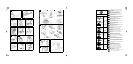
Supply of the nylon string - B
In order to extend the nylon line as it wears down, pull the
mower gauge downwards and turn it in a clockwise
direction to feed out the desired length of line.
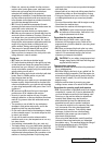
F6. Attachments fitting/removal (for split shaft
models only)
1) Loosen the joint knob first, then insert attachment’s
shaft into the shaft/attachment joint (1) and make
sure that the locking pin(A) is secured in one of its
housings, finally lock firmly the joint knob(B).
2) To remove the attachment from the power unit:
loosen the joint knob(1), push the locking pin (2) and,
keeping it pressed, remove attachment’s shaft from
the joint(3).
3) Every attachment manual explains through a picture
in which ways each attachment can be assembled
on the power unit: a configuration is forbidden if
crossed ,if marked with “NO” and/or the symbol,
or if it isn’t shown at all. A configuration is allowed if
marked with “OK” and/or the symbol.
The figure shows assembling configurations allowed for
the string head/grass blade attachment (with the rules
defined in the previous paragraph, it is forbidden to
assemble the string head/grass blade attachment with
the locking pin in both left and right housings, allowing its
assembling in the upper housing only).
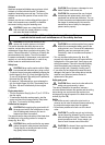
G1. Double handle
Adjust and secure double hand clamp by tightening the
screws.
G2. Delta handle
For your safety, fasten the delta handle in front of the
label placed on the shaft at a distance of at least 11 cm
from the rear grip. The handle should be fastened in a
comfortable working position. The safety pole guard
should be mounted using the accessories supplied and in
the configuration shown in the figure, in contact with the
delta handle.
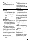
Cold engine starting
•
H1.
Move stop switch to the “ON” position.
•
H2.
Depress the safety lever (
S
), squeeze the
accelerator trigger (
A
) and push the throttle advance
forwards (
B
). Now release the accelerator trigger (
A
)
and then the throttle advance (
B
).
•
H3.
Move choke lever (
E
) to the closed position .
•
H4.
Press the primer bulb (
C
) several times until you
see fuel going back to carburetor through pipe (
D
). Pull
starter rope until engine fires once.
•
H5.
Move choke lever (
E
) to the open position then
pull starter rope until engine fires. Let engine run for a
few seconds holding the trimmer. Now disengage
throttle advance by pulling trigger completely. Engine
will now keep on running at idle speed.
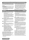
Hot engine starting
STOP switch on START position I. Trigger on idle
position (released). Choke towards (open position ).
Press the primer bulb (
C
) several times until you see fuel
going back to carburetor through pipe (
D
). Pull starter
rope.
H6. Engine stopping
Press the stop switch moving it to STOP position “0”.
G. Assembly of grips
H. Starting and stopping the engine
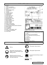
ƽ
CAUTION!
First read chapter “Safety
Precautions”
ƽ
CAUTION!
Start the brush cutter in a flat place.
During startup stand in a stable position. Make
sure the blade or nylon string head do not touch
the ground or any obstacles.
ƽ
CAUTION!
Grip the knob of the starter with one
hand and hold the machine in a stable position
with the other. (Take care not to wind the starter
string around your hand) and pull slowly until you
encounter some resistance, then pull the cord
sharply and forcefully (to start the engine when
cold or warm follow the procedures described).
ƽ
CAUTION!
Do not pull the starter cord all the way
and do not release it abruptly against the machine
as this could damage it.
ƽ
CAUTION!
When the throttle advance is
engaged, the head or blade rotates.
ƽ
CAUTION!
When the throttle (
B
) advance is
engaged, the head or blade rotates.
ƽ
CAUTION!
When the engine is switched off
rotating parts, blade or nylon string head, will
keep on rotating for a few seconds. Hold the
machine until all parts come to a standstill.
ƽ
CAUTION!
In an emergency the above
mentioned delay in stopping may be shortened by
touching blade parallel on the ground.