


Gr a s s Tr i m m e r /Br u s h Cu T T e r
13
Op e r a T O r 's ma n u a l
C
A
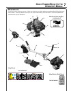
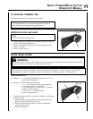
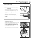
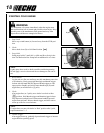
u-h a n d l e I n s t a l l a t I o n
Tools Required: 17 & 19 mm wrench, 4 mm hex socket wrench
Parts Required: U-Handle, Clamp w/screws, 8 mm x 55 mm hex
bolt,
8 mm at washer
1. Install upper U-Handle and bracket on lower bracket with one
(1) 8mm x 55mm bolt (A) and (1) large circular washer. Do not
tighten bolt securely until nal adjustments are completed.
2. Loosen upper (2) U-handle clamp screws (B), and position U-
handle as shown.
3. Lightly tighten 8mm bolt (A) and clamp screws (B) to hold U-
handle in position until nal adjustments are completed.
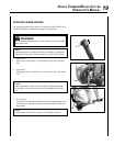
4. Route throttle linkage and ignition lead assembly along shaft and
clip as shown.
5. Install throttle linkage cable into fan cover clip (C).
B
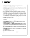
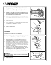
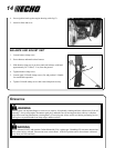
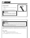
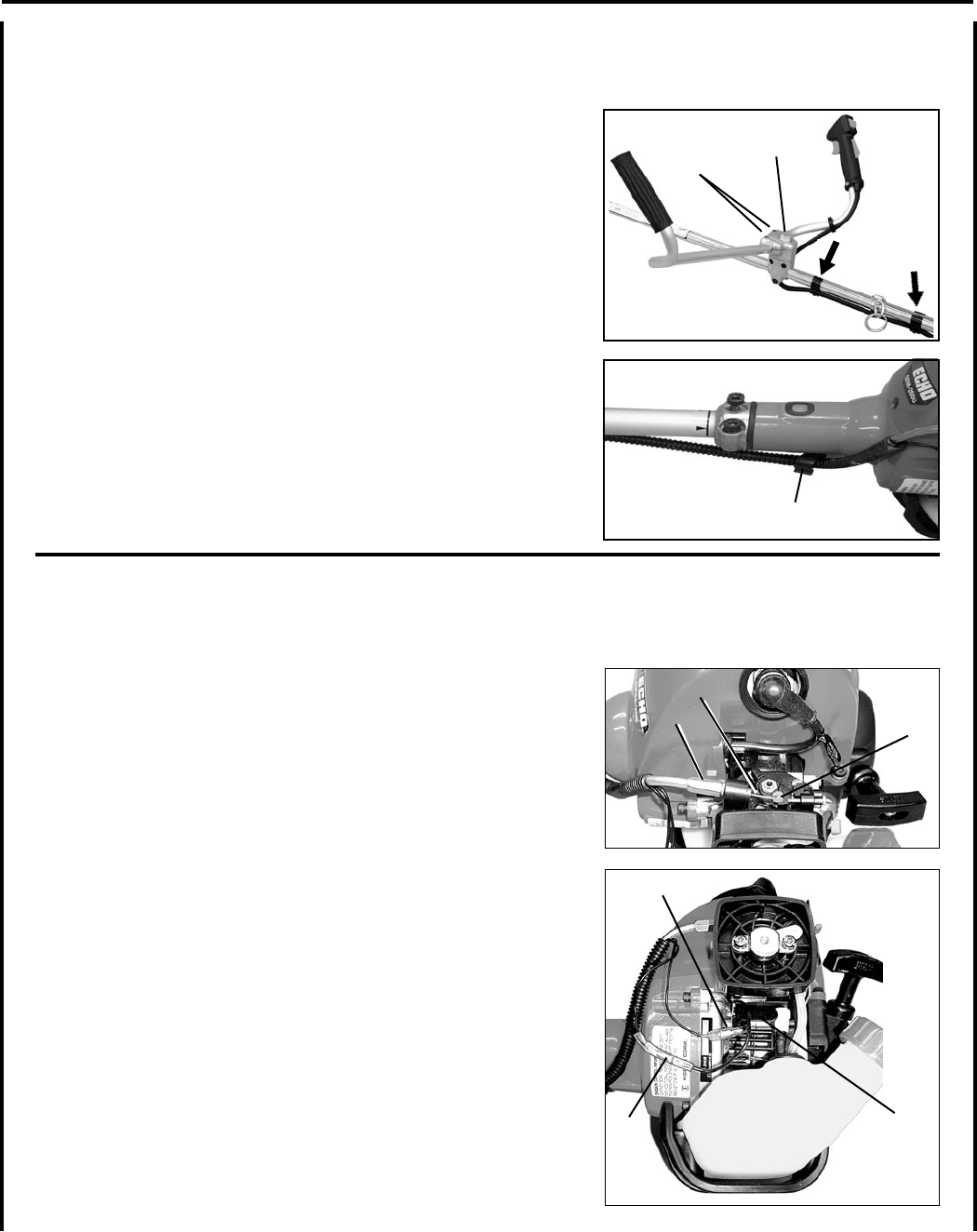
t h r o t t l e l I n k a g e a n d IgnItIon l e a d s
1. Close choke and remove air lter cover.
2. Place throttle linkage (A) through adjustment xture (B) and install
wire end into large carburetor throttle swivel hole (C). Check
throttle for freedom of movement and that wide open throttle / low
idle extremes are adjusted properly. The throttle linkage must be
adjusted by moving the adjustment xture (B). Consult with your
Echo Dealer for correct adjustment procedure.
3. Connect 2 ignition stop leads (D,E) from throttle cable tubing to 2
ignition leads (D,E) on engine.
A
B
D
E
F
C