


GRASS TRIMMER/BRUSH CUTTER
OPERATOR'S MANUAL
11
H
D
I
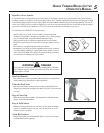
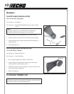
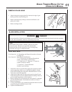
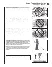
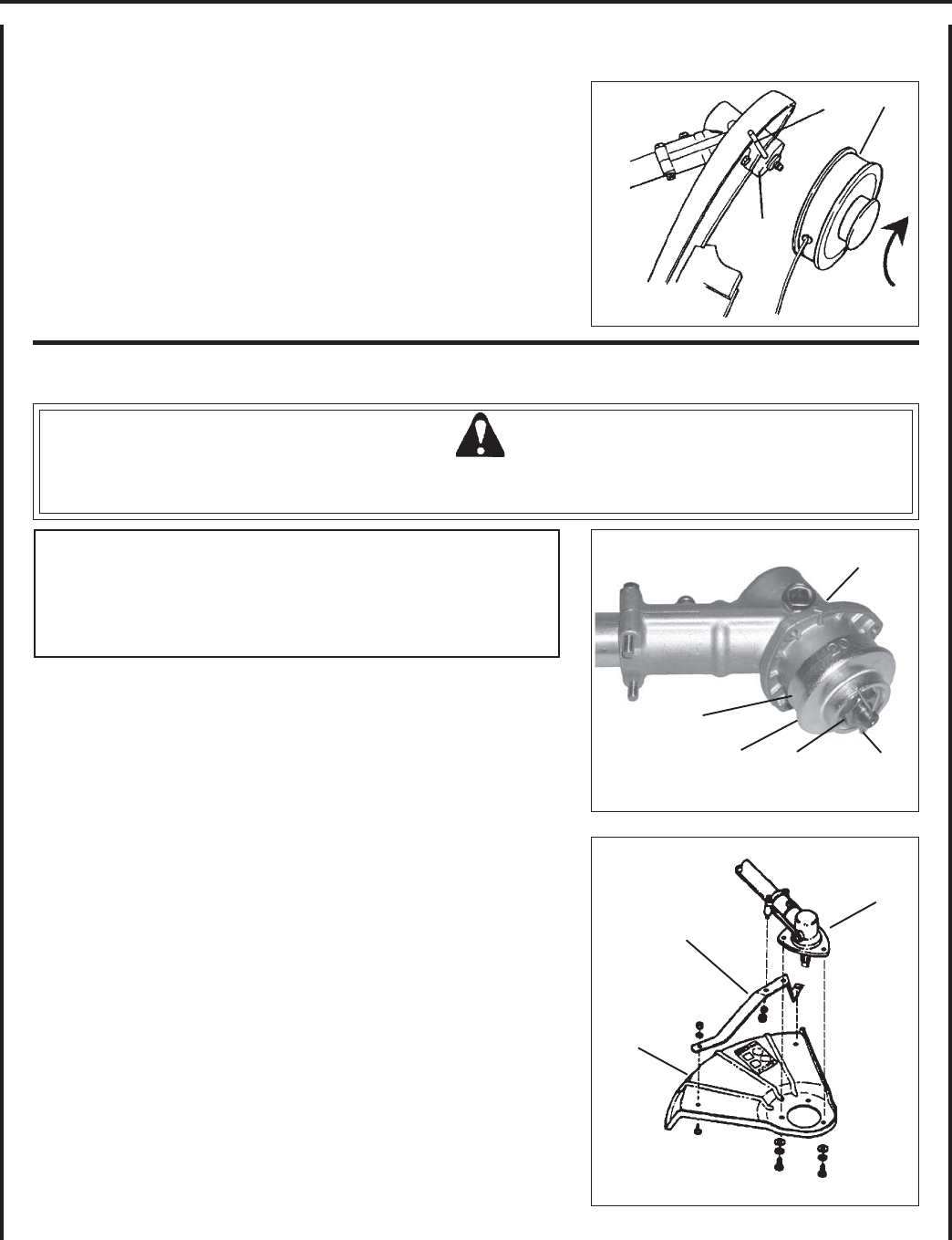
REMOVE NYLON HEAD
1. Align locking hole in upper plate (D) with notch in edge of gear
housing and insert head locking tool.
2. Remove line head (I) by turning it clockwise until head is com-
pletely off of shaft.
3. Remove locking tool (H).
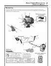
BLADE INSTALLATION
WARNING DANGER
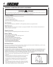
You must install the U-Handle and all Blade Conversion parts shown in the following instructions before operating
this unit with a metal blade, otherwise serious injury may result.
NOTE
Model SRM-230U includes U-Handle, and necessary blade
conversion parts. Blades are not provided with trimmer/
brushcutters and must be selected for type of cutting being
performed. See page 15, "Blade Selection."
Install Metal Shield
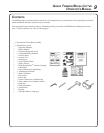
Tools Required: 8 x 10 mm Open-end Wrench, Screwdriver, Scrench,
Locking Tool
Parts Required: Metal Shield, Shield Bracket,
3 - 5 x 15 mm screws w/captivated flat and lock-
washer, (metal shield to gear housing).
2 - 5 x 8 mm screws, 2 - 5 mm nuts, 2 - 5 mm lock-
washers, (bracket to shield).
2 - 5 mm nuts, 2 - 5 mm lockwashers
(bracket to gear housing)
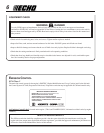
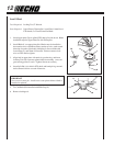
1. If installed, remove nylon line head, upper plate and plastic shield,
and set upper plate aside for use with blade installation. Retain
plastic shield, shield plate, and plastic shield hardware for conver-
sion back to nylon line operation.
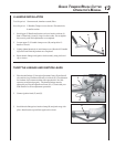
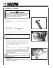
2. Align hole in upper plate (D) with notch in gear housing (G), and
insert locking tool to prevent splined shaft from turning. Arrow on
gear housing flange points to notch location.
3. Remove split pin (A), L.H. blade nut (B), lower plate (C), and upper
plate (D) from PTO shaft. Turn blade nut clockwise to remove.
4. Remove locking tool.
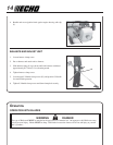
5. Loosely attach bracket (J) to shield (K) and attach shield to bottom
of gear housing (G) with hardware provided.
6. Tighten all shield hardware.
K
J
G
C
B
A
D
G