


8
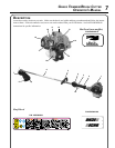
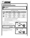
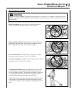
1. POWER HEAD - Includes the Engine, Clutch, Fuel System, Ignition System and Recoil Starter.
2. GRIP - Rear (right hand) handle.
3 THROTTLE TRIGGER LOCKOUT - This lever must be held during starting. Operation of the throttle trigger is
prevented unless throttle trigger lockout lever is engaged.
4. STOP SWITCH - "SLIDE SWITCH" mounted on top of the Throttle Trigger Housing. Move switch FORWARD
to RUN, BACK to STOP.
5. FRONT HANDLE - The Front (loop) handle is loosely assembled to the Drive Shaft assembly and must be posi-
tioned for proper cutting attitude and operator comfort.
6. DRIVE SHAFT ASSEMBLY - Includes the Rear (right hand) Handle assembly, Gear Housing assembly, Front
(loop, left hand) Handle assembly, steel drive shaft and Safety Decal.
7. NYLON CUTTER HEAD - Contains replaceable nylon trimming line that advances when the trimmer head is
tapped against the ground while the head is turning at normal operating speed.
8. CUT-OFF KNIFE - Automatically trims line to the correct length: 5" after head is tapped on the ground. If trimmer
is operated without a cut-off knife, the line will become too long, the engine will overheat, and engine damage may
occur.
9. PLASTIC DEBRIS SHIELD ASSEMBLY - Included in plastic bag (co-pack). MUST be installed on unit before
use, see Assembly Instructions. Shield assembly includes the Cut-Off Knife. Mounts on the Gear Housing Assem-
bly just above the cutting attachment. Helps protect the operator by deecting debris produced during the trimming
operation. This shield must be replaced with the steel shield for blade use.
10. THROTTLE TRIGGER - Spring loaded to return to idle when released. During acceleration, press trigger gradu-
ally for best operating technique.
11. SPARK PLUG - Provides spark to ignite fuel mixture.
12. ARM REST - Provides arm rest during operation and protects arm from the hot engine.
13. RECOIL STARTER HANDLE - Pull handle slowly until starter engages, then quickly and rmly. When engine
starts, return handle slowly. DO NOT let handle snap back or damage to unit will occur.
14. SPARK ARRESTOR MUFFLER OR SPARK ARRESTOR MUFFLER WITH CATALYST -The mufer or
catalytic mufer controls exhaust noise and emission. The spark arrestor screen prevents hot, glowing particles of
carbon from leaving the mufer. Keep exhaust area clear of ammable debris.
15. FUEL TANK - Contains fuel and fuel lter.
16. FUEL TANK CAP - Covers and seals fuel tank opening.
17. CHOKE - The choke control is located on the top of the air lter case. Move choke lever to "Cold Start" ( ) to
close choke for cold start. Move choke lever to "Run" ( ) position to open choke.
18. AIR CLEANER - Contains replaceable lter element.
19. PURGE BULB - Pumping purge bulb before starting engine draws fresh fuel from the fuel tank, purging air from
the carburetor. Pump purge bulb until fuel is visible and ows freely in the clear fuel tank return line. Pump purge
bulb an additional 4 or 5 times.