


8
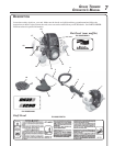
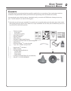
1. POWER HEAD - Factory Assembled to the Drive Shaft assembly. Includes the Engine, Clutch, Fuel System, Ignition
System and Recoil Starter.
2. GRIP - Rear (right hand) handle.
3. STOP SWITCH - "SLIDE SWITCH" mounted on top of the Throttle Trigger Housing. Move switch FORWARD to
RUN, BACK to STOP.
4. FRONT HANDLE - The Front (loop) handle is factory assembled to the Drive Shaft assembly but must be reposi-
tioned for proper cutting attitude and operator comfort.
5. DRIVE SHAFT ASSEMBLY - Factory Assembled to the Power Head. Includes the Rear (right hand) Handle
Assembly, Bearing Housing Assembly, Throttle Trigger, Front (loop, left hand) Handle Assembly, Flexible Drive
Cable and Safety Decals.
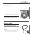
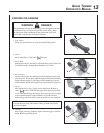
6. RAPID LOADER
TM
HEAD - Contains replaceable nylon trimming lines.
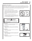
7. CUT-OFF KNIFE - Trims line to the correct length (5 in.). If trimmer is operated without a cut-off knife the line will
become too long - more than (5 in.) - the operating speed will slow, the engine overheat and performance will suffer.
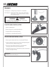
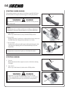
8. DEBRIS SHIELD ASSEMBLY - Included in plastic bag (co-pack). MUST be installed on unit before use, see
Assembly Instructions. Shield assembly includes the Cut-Off Knife and Safety Decal. Mounts on the Bearing
Housing Assembly just above the cutting attachment. Helps protect the operator by deflecting debris produced
during the trimming operation.
9. THROTTLE TRIGGER - Spring loaded to return to idle when released. During acceleration, press trigger gradually
for best operating technique.
10. SHOULDER HARNESS - Optional (P/N 99944200201). An adjustable strap that suspends the unit from the operator.
11. SPARK ARRESTOR - CATALYTIC MUFFLER / MUFFLER -The muffler or catalytic muffler controls exhaust noise
and emission. The spark arrestor screen prevents hot, glowing particles of carbon from leaving the muffler. Keep
exhaust area clear of flammable debris.
12. FUEL TANK - Contains fuel and fuel filter.
13. I-30 RECOIL STARTER/HANDLE - i30 spring-assisted recoil starter requires 30% less pulling force than standard
recoil starter. Pull handle slowly until starter engages, then quickly and firmly. When engine starts, return handle
slowly. DO NOT let handle snap back or damage to unit will occur.
14. FUEL TANK CAP - Cover and seals fuel tank opening.
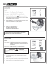
15. CHOKE - Located at the rear of the air cleaner housing. Move choke lever to "Cold Start" ( ) to close choke for
cold starting. Move choke lever to "Run" ( ) position to open choke.
16. AIR CLEANER - Contains replaceable filter element.
17. PURGE BULB - Pumping purge bulb before starting engine draws fresh fuel from the fuel tank, purging air from the
carburetor. Pump purge bulb until fuel is visible and flows freely in the clear fuel tank return line. Pump purge bulb
an additional 4 or 5 times.
18. SPARK PLUG - Provides spark to ignite fuel mixture.