21
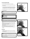
B
C
D
E
F
G
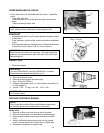
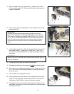
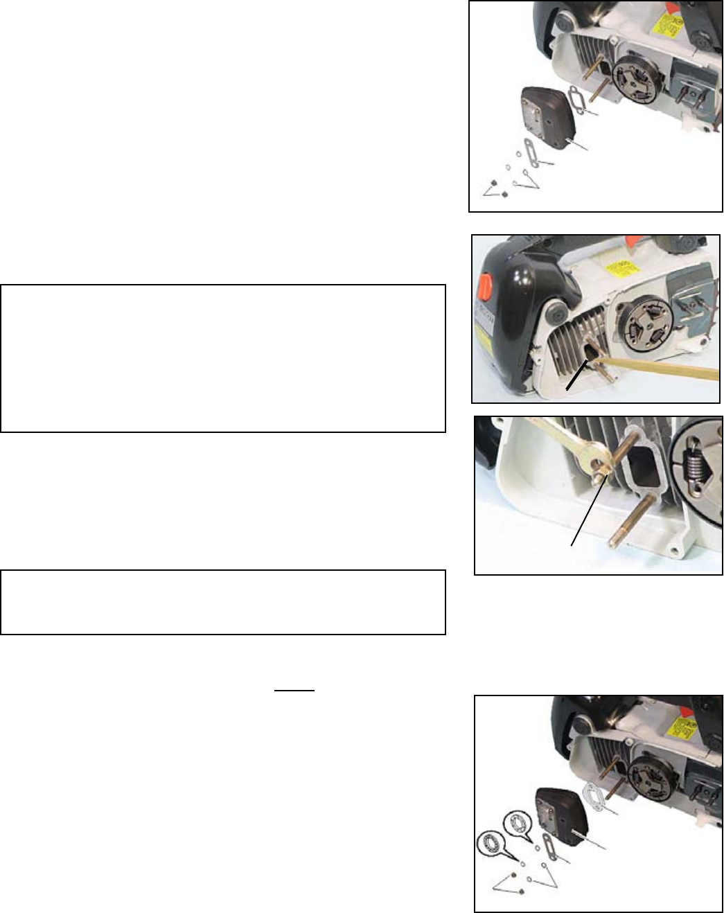
6. Use a wood or plastic scraping tool to clean deposits from cylinder
exhaust ports (G).
5. Remove mufer nuts (B), washer sets (C), eyeplate (D), mufer
(E), and mufer gasket (F). Check parts for wear or damage, and
replace if necessary.
IMPORTANT
If mufer mounting studs loosened during mufer nut removal,
tighten studs using two nuts (H) tightened together on end of stud.
Turn outer nut clockwise, and tighten stud to 70 kgf • cm (7 N-m, 60
in • lbf). Do not exceed specications, otherwise stud damage may
occur. To remove nuts, hold inner nut, and turn outer nut counter
clockwise to remove, then turn inner nut counter clockwise to re-
move.
7. Install mufer gasket (F), mufer (E), eyeplate (D), washer sets (C),
and mufer nuts (B). Tighten nuts to 70 kgf • cm (7 N-m, 60 in •
lbf), but do not exceed specications, otherwise damage to studs
may occur.
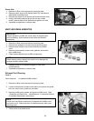
IMPORTANT
Washer sets must be installed with serrated surfaces facing apart, as
shown in illustration.
8. Connect spark plug lead and replace air lter cover.
H
9. Start engine, and allow unit to warm up at idle for several minutes.
10. Stop engine, and re-tighten mounting nuts to to 70 kgf • cm (7 N-m,
60 in • lbf), but do not exceed specications, otherwise damage to
studs may occur.
11. Install mufer cover and tighten screws.
12. Install guide bar and chain, clutch cover, and guide bar nuts, tight-
ening nuts until nger tight. Adjust chain tension as instructed in
“Adjustment, Chain Tension” section of instruction manual.
13. Start engine and check for exhaust leaks between mufer and cyl-
inder head. Stop engine if leak is found and correct problem before
operating chain saw.
B
C
D
E
F


