


12 X7532095608
© 3/2015 ECHO Inc.
ASSEMBLY 99944200595
ASSEMBLY
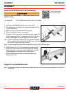
Power Head Shaft/Lower Shaft Assembly
Do not perform maintenance or assembly procedures with
engine running.
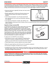
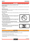
1. Set Power Head/Shaft Assembly on a level surface.
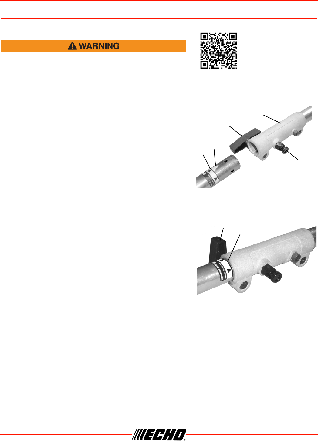
2. Pull locator pin (A) out, and turn counter-clockwise 1/4 turn
to lock-out position.
3. Remove vinyl cap from attachment drive shaft.
4. Remove cardboard spacer, if necessary.
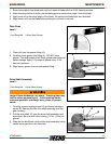
5. Carefully fit attachment drive shaft assembly into coupler (B)
to decal assembly line (C), making sure that the inner lower
drive shaft engages the square upper drive shaft socket.
Note: Earlier model Power Heads may have shorter couplings.
Short couplings fit flush to decal point (E). New couplings
are 4-3/4 in. long, and fit flush to line (C).
Note: Lower bearing housing and head assembly must be in line with the engine.
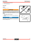
6. Rotate locator pin (A) 1/4 turn clockwise to engage lower
shaft hole. Insure locator pin is fully engaged by twisting
lower drive shaft. Locator pin should snap flush in coupler.
Full engagement will prevent further shaft rotation.
7. Secure lower shaft assembly to coupler by tightening
clamping knob (D).
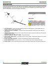
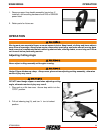
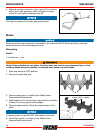
Support Loop Handle Removal
Note: Support loop handles or support loop handles with barrier bars are not recommended for use with this
attachment.
Parts Required: PAS or SRM-SB Power Head w/Shaft & Coupling
For more information
scan this QR code.
A
B
D
E
C
C
D