


9/89 (Revised)
Page 1
TECHNICAL DATA BROCHURE
(MODEL ZTR 304)
IMPORTANT - READ OPERATOR'S MANUAL BEFORE OPERATING OR MAKING ADJUSTMENTS
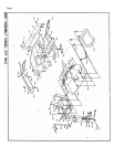
BODY REMOVAL
1. The 304 has a (2) piece fabricated steel body. The upper body can be folded
forward to expose the transaxle. In some cases, it may be necessary to remove
the upper body to service the transaxle.
\
2.
To remove upper body, fold forward and remove bolt (P/N 3006) from cable (P/N
3780). Shut upper body and remove the two cotter pines (P/N 3058) from the
front of upper body support. Carefully lift upper body from frame.
3. Reverse above procedure to reinstall.
SEAT ADJUSTMENT
1. Raise upper body.
2.
Loosen four seat bolts (P/N 3093) and slide seat forward or backward to
desired position.
3. Retighten bolts.
MOWER BLADE OPERATION
To engage the mower blades, turn lever on floor slowly to the "ON" position. To
disengage mower blades, turn lever slowly to the "OFF" position.
REMOVING MOWER DECK *
1. Loosen the belt keeper (P/N 7026 & 7027), located under the engine, by loosing
two rear engine mounting bolts, allowing the deck drive belt to come free of the
rear pulley.
2. Disconnect the wiring loom at the deck safety switch (P/N 4242).
3. Remove* the two clevis pins (P/N 3072) from the two rear L-rods (P/N 1355) and
slide from slots.
4. Remove clevis pins (P/N 3072) L-rod attached to lift handle and slide from
slot.
5. Remove clevis pin (P/N 3072) from front deck hanger' shaft (P/N 1332), located at
from of mower deck on slide plates welded at battery box and remove.
6. Lift front of mower chassis and roll free of the deck.
7. To install, reverse the above procedure.
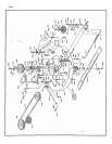
IDJUSTMENT OF MOWER DECK DRIVE BELT
1. The mower deck drive belt is tensioned by a spring loaded engagement idler
quadrant.
2. This system is designed to maintain the proper belt tension at all times.
3. Belt tension can be adjusted by moving the engaging rod (P/N 7013) into the
outside hole of engagement handle (P/N 7020).
4. After belt tension is adjusted, check to assure that the mower blade will not
turn freely when the engaging rod is in the "OFF" position.
5. If the mower blade .urns freely, adjust the blade by loosening*nut' (P/N 3205) at
end of the brake linkage (P/N 7015).
6. After adjustment is achieved, perform the safety checks listed below.