


17
Dixon Industries, Inc. • Airport Industrial Park • Coffeyville, KS • 67337 • 620-251-2000
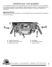
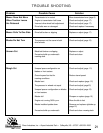
SERVICE ADJUSTMENTS
DANGER: BEFORE MAKING ANY ADJUSTMENTS AND/OR SERVICING YOUR MOWER, MAKE SURE
THE MOWER IS ON LEVEL GROUND, BLADES DISENGAGED, KEY REMOVED, AND THE ENGINE OFF
WITH THE SPARK PLUG WIRE(S) REMOVED FROM THE SPARK PLUG(S) TO PREVENT ACCIDENTAL
CONTACT. IF ADJUSTMENTS OR MAINTENANCE IS BEING PERFORMED AFTER OPERATION OF THE
MOWER, ALLOW THE UNIT TO COOL SINCE HEAT BUILD UP COULD CAUSE SEVERE BURNS.
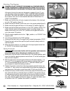
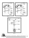
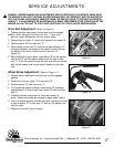
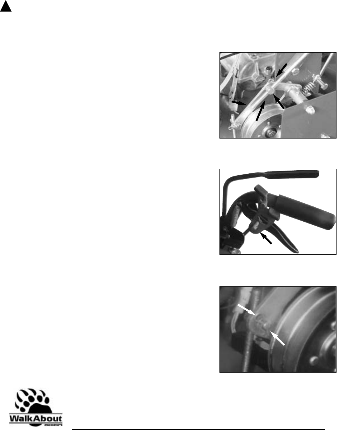
Drive Belt Adjustment: (Refer to Figure 9)
1. Release the right side traction control lever into the engaged
position. Move the gear shift lever into first “1” gear, and
pull the mower backwards until the mower stops.
2. Remove hair pin cotter “A” and the flat washer from swivel “B”.
3. Remove swivel “B” from idler arm “C”.
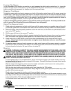
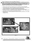
4. Move traction control rod “D” until there is approximately 1/2”
clearance between the bottom of the traction control rod and
the bottom of the slot in traction control lever lock “A”
(figure 10).
5. While holding the rod in place, rotate swivel “B” on the traction
control rod “D” until the swivel realigns with the hole in idler
arm “C”. Push the swivel through the idler arm hole and secure
with the flat washer and hair pin cotter. Repeat for the other
side.
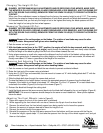
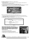
Wheel Brake Adjustment: (Refer to Figure 11)
1. Release the left side traction control lever into the engaged
position.
2. Remove the hair pin cotter “A” from swivel “B”.
3. Remove swivel “B” from idler arm “C”.
4. To increase the amount of brake, rotate swivel “B” clockwise
approximately 2 to 3 turns and insert swivel “B” back into idler
arm “C”.
5. Check the traction control lever for the proper amount of
brake. Should more brake be necessary, repeat steps 3 and 4.
6. Once the proper amount of brake has been achieved, be sure
to secure swivel ”B” to idler arm “C” with the flat washer and
hair pin cotter.
7. Repeat for the other side if needed.
!
Figure 9
Figure 10
A
Figure 11
A
C
B
A
B
C
D