10
ASSEMBLY
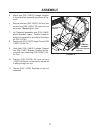
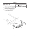
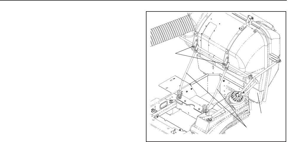
5. Attach two (539 114812) Linkage, Support
to the clamshell assembly as shown in Fig-
ure 6.
6. Secure with two (539 100476) 5/8 hex jam
nut and two (539 115591) 5/8 nyloc hex nut
as shown. Do not tighten nuts.
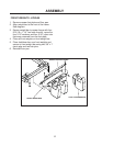
7. Lift Clamshell assembly onto (539 114815)
Mount Bracket, Lower. Position tubes on
bottom of clamshell on out side of the tubes
on (539 114781).
8. Secure with (539 119372) Hinge Pin and (539
115501) Cotter Pin.
9. Hook both (539 114812) Linkage, Support
into (539 114811) Bracket, Support and se-
cure with two remaining (539 115501) Cot-
ter Pins.
10. Tighten (539 100476) 5/8 Jam nut and
(115591) 5/8 Nyloc nut so that the clamshell
is sitting straight on unit.
11. Tighten (539 114782) Brackets on front of
clamshell.
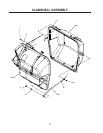
CLAMSHELL
ASSEMBLY
539 114812 LINKAGE,
SUPPORT
FIGURE 6
539 114782
BRACKET


