


6
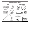
Your new tractor has been assembled at the factory with exception of those parts left unassembled for shipping purposes.
To ensure safe and proper operation of your tractor all parts and hardware you assemble must be tightened securely. Use
the correct tools as necessary to ensure proper tightness.
TOOLS REQUIRED FOR ASSEMBLY
A socket wrench set will make assembly easier. Stan dard
wrench sizes are listed.
(2) 7/16" wrenches Utility knife
(1) 1/2" wrench Tire pressure gauge
(1) 3/4" wrench Pliers
(1) 3/4" socket w/drive ratchet
When right or left hand is mentioned in this man ual, it means
when you are in the operating po si tion (seated be hind the
steer ing wheel).
TO REMOVE TRACTOR FROM CARTON
UNPACK CARTON
• Remove all accessible loose parts and parts cartons
from carton .
• Cut along dotted lines on all four panels of carton.
Remove end panels and lay side panels flat.
• Remove mower and packing materials.
• Check for any additional loose parts or cartons and
remove.
BEFORE REMOVING TRACTOR FROM
SKID
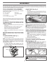
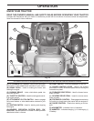
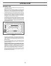
TO CHECK BATTERY (See Fig. 1)
• Lift hood to raised position.
NOTE: If this battery is put into service after month and
year indicated on label (label is located between terminals)
charge battery for minimum of one hour at 6-10 amps.
(See "BATTERY" in Maintenance section of this manual
for charging instructions).
• For battery and battery cable installation see "RE-
PLACING BATTERY" in the "Service and Adjustments"
section in this manual.
Fig. 1
LABEL
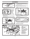
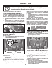
ADJUST SEAT (See Fig. 2)
• Sit in seat.
• Lift up adjustment lever (A) and slide seat until a com-
fortable position is reached which allows you to press
clutch/brake pedal all the way down.
• Release lever to lock seat in position.
Fig. 2
NOTE: You may now roll your tractor off the skid. Follow the
instructions below to remove the tractor from the skid.
WARNING: Before start ing, read, un der stand and fol low
all in struc tions in the Op er a tion section of this man u al. Be
sure tractor is in a well-ventilated area. Be sure the area in
front of tractor is clear of other peo ple and objects.
TO ROLL TRACTOR OFF SKID (See Op er a tion
section for location and function of con trols)
• Raise attachment lift lever to its highest po si tion.
• Release parking brake by de press ing clutch/brake
ped al.
• Place freewheel control in "trans mis sion dis en gaged"
position (See “TO TRANS PORT” in the Op er a tion
section of this manual).
• Roll tractor forward off skid.
Continue with the instructions that follow.
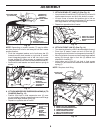
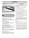
TO INSTALL MOWER AND BLADE DRIVE
BELT (See Figs. 3 - 16)
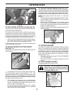
1. SET PARKING BRAKE LEVER AND LOWER AT-
TACHMENT LIFT LEVER (See Fig. 3 and 4)
• Depress clutch/brake pedal all the way down and hold.
• Pull parking brake lever up and hold, re lease pres sure
from clutch/brake pedal, then release parking brake
lever. Pedal should re main in brake position. Ensure
parking brake will hold tractor secure.
PARKING
BRAKE
LEVER
Fig. 3
CAUTION: Lift lever is spring loaded. Have a
tight grip on lift lever, lower it slowly and en-
gage in lowest position. Lift lever is located
on left side of fender.
A
ASSEMBLY