BODY REMOVAL
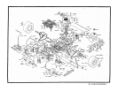
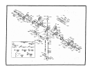
1. The 361 has a two -piece polyethylene body. The upper body can be folded forward to
expose the transaxle. In some cases. It may be necessary to remove the upper body to
service the transaxle.
2. To remove upper body, remove two bolts P/N 3093 from the front of upper body hinge
located on the brake shaft P/N 9283. Disconnect seat switch P/N.4761 at plug-in.
3. Reverse above procedure to reinstall.
ADJUSTMENT OF MOWER DECK DRIVE BELT
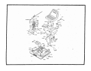
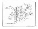
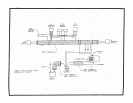
Belt tension is controlled and adjusted by tightening nut P/N 3205 on L -rod P/N 2841 as shown In the
illustration. Proper belt tension can be measured by pushing against belt at mid-point on the left side
of the mower chassis. Belt should deflect approximately 3/4" to 1" when adjusted.
REMOVING MOWER BLADES
1. Secure mower blade P/N 1324 from turning.
2. Observe blade position when removing.
3. Remove blade bolt P/N 3268, and blade washer P/N 6260.
4. To reinstall, reverse above procedure. Tighten to 50-60 ft pounds of torque.
WARNING: Sharp edges on blade can cause injury!
Caution should be exercised when service Is required on the blade.
REMOVING MOWER DECK
1. Remove deck drive belt by loosing nylok nut P/N 3205 on L-Rod tensioner P/N 2841 until belt
can be removed from electric clinch.
2. Remove the clevis pins P/N 3072 from L-rods at rear of deck and slide free from slots.
3. Remove the clevis pin P/N 3072 from the lift linkage at the front of deck.
4. Remove cotter pin from shaft P/N 1332 located at front of mower deck on slide plates
welded at battery box. Slide shaft free.
5. Raise front of mower chassis and roll mower free of mower deck assembly.
6. To install deck, reverse above procedure.


