


11
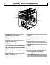
GENERAL PARTS IDENTIFICATION
1. Frame assembly- Protects generator and engine as
well as a means to handle complete unit.
2. Fuel Tank- Six (6) gallon capacity.
3. Fuel Cap- Remove to check/add fuel.
4. Cover Panel- Contains wiring for receptacles, circuit
breakers, and control switches.
5. 120V 15 Amp Duplex Receptacle.
6. 125/250V 20 Amp Circuit Breaker.
7. 120V 30 Amp Single 3-Prong Twistlock Receptacle.
8. 240V 20 Amp Single 3-Prong Twistlock Receptacle.
9. "Off"/"On"/Start Switch"- Switch must be set to "On"
position to start engine manually, depress "Start" if
batttery starter is to be used, and in "Off" position
to shut engine "Off".
10. Full Power Switch- Allows use of 120v only or com-
bination of 120V and 240V use.
11. Battery Frame- Holds battery for electrical start.
12. Vibration Isolator- Isolators reduce engine vibration to
the frame.
13. Generator Housing- Houses the electrical generating
components.
14. Oil Filler Cap/Dipstick- For checking and adding oil.
15. Oil Drain Plug- Removal allows oil to be drained/
changed in the engine. Refer to the Engine Operator's
Manual for maintenance intervals.
16. Vibration Isolator- Isolators reduce engine vibration to
the frame.
17. Fuel Shutoff Valve- Controls flow of fuel to engine.
18. Fuel Filter- Filters fuel before entering engine.
19. Air Filter- Contains paper type element. Refer to the
Engine Operator's Manual for maintenance.
20. Exhaust Muffler- (*See Note Below).
21. 9 HP Briggs & Stratton Engine- Included with this gen-
erator is a copy of the Engine Manufacturer's Operator's
Manual. See this manual for more detail on the engine.