


11 - ENG
A16091
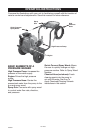
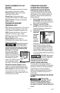
BASIC ELEMENTS OF AN
ENGINE
Refer to the engine manual for location
and operation of engine controls.
Choke Control: Opens and closes
carburetor choke valve.
Starter Grip: Pulling starter grip
operates recoil starter to crank engine.
Engine Switch: Enables and disables
ignition system.
PRESSURE WASHER
TERMINOLOGY
PSI: Pounds per Square Inch. The unit of
measure for water pressure. Also used
for air pressure, hydraulic pressure, etc.
GPM: Gallons Per Minute. The unit of
measure for the flow rate of water.
CU: Cleaning Units. GPM multiplied by
PSI. GPM x PSI = CU
Bypass Mode: Allows water to
re-circulate within pump when the gun
trigger is not pulled.
Allowing the unit to
run for more than
two minutes without the gun trigger
pulled could cause overheating and
damage to the pump.
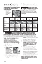
Thermal Relief Valve:
When the temperature
inside the pump rises too
high the valve will open
and release a gush of
water in an effort to lower
the temperature inside
the pump. The valve will then close.
Chemical Injection System: Mixes
cleaners or cleaning solvents with the
water to improve cleaning effectiveness.
Water Supply: All pressure washers must
have a source of water. The minimum
requirements for a water supply are 20 PSI
and 5 gallons per minute.
PRESSURE WASHER
OPERATING FEATURES
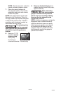
PRESSURE ADJUSTMENTS
The pressure setting is preset at the
factory to achieve op ti mum pres sure
and cleaning. If you need to lower the
pres sure, it can be accomplished by
these meth ods.
1. Back away from the sur face to
be cleaned. The further away you
are, the less the pressure will be on
the surface to be cleaned.
2. Change to the 40º nozzle -
(white) this nozzle delivers a less
powerful stream of water and a
wider spray pattern.
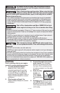
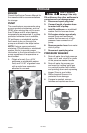
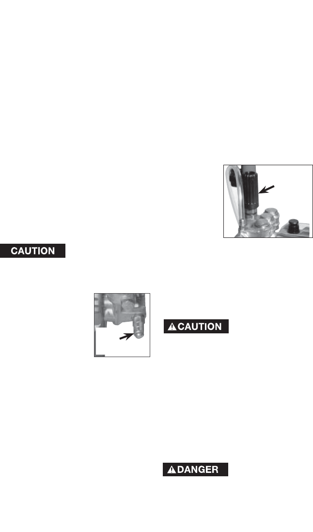
3. Adjust the
pres sure
reg u la tor
on the
pump.
Turn the
pressure
reg u la tor
knob coun-
ter clock wise to lower pressure.
Re fer to the illustrations to iden ti fy
your pres sure reg u la tor. Once you
have fin ished using your pres sure
wash er, re turn the pres sure reg u la-
tor to its original position by turning
it clock wise.
DO NOT try to turn
pressure regulator
knob past the built-in stop or
damage to pump will result.
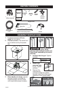
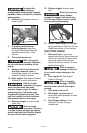
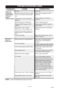
SPRAY WAND NOZZLES
The nozzles for the spray wand are
stored in the nozzle holder on the panel
assembly. Colors on the panel identify
nozzle location and spray pattern.
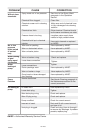
Refer to the following chart to choose
the correct nozzle for the job to be
performed.
CHANGING NOZZLES ON SPRAY
WAND
Risk of fluid
injection. Do not
direct discharge stream toward
persons, unprotected skin, eyes or
any pets or animals. Serious injury will
occur.
Thermal
Relief
Valve
Pressure
Regulator
Knob