www.desatech.com
115481-01B 15
SPECIFICATIONS
HCA-24-RFN HCA-24-RFP HCA-18-RFN HCA-18-RFP
HCM-24-RFN HCM-24-RFP HCM-18-RFN HCM-18-RFP
HKE-24-RFN HKE-24-RFP HKE-18-RFN HKE-18-RFP
Btu (Variable) 45,000/67,000 43,000/65,000 41,000/56,000 42,000/51,000
Type Gas Natural Gas Only Propane/LP Only Natural Gas Only Propane/LP Only
Ignition Piezo Piezo Piezo Piezo
Manifold Pressure 3.5" - 1.6"W.C. 10" - 6.3"W.C. 3.5" - 1.6"W.C. 10" - 6.3"W.C.
Inlet Gas Pressure (in. of water)
Maximum 10.5" W.C. 13" W.C. 10.5" W.C. 13" W.C.
Minimum* 5.0" W.C. 11" W.C. 5.0" W.C. 11" W.C.
Valve Operation RF Millivolt RF Millivolt RF Millivolt RF Millivolt
Orifice Size #21 #42 #28 #45
* For purpose of input adjustment
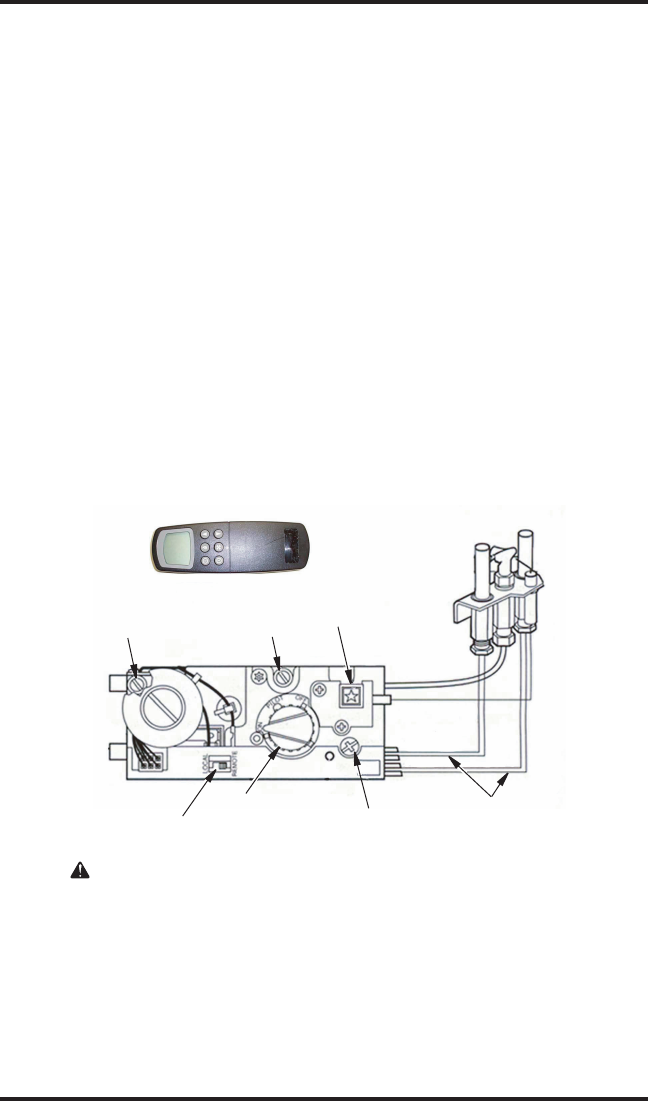
WIRING DIAGRAM
Outlet
Pressure
Tap
Inlet
Pressure
Tap
Piezo
Gas Control
Knob
Pilot
Adjustment
Screw
Pilot
Burner
Assembly
Pilot Tube
Thermopile
Leadwires
Local and
Remote Switch
REMOTE CONTROL
(MILLIVOLT)
POWER SUPPLY. PROVIDE
DISCONNECT MEANS AND
OVERLOAD PROTECTION AS
REQUIRED.
Figure 16 - Millivolt System Wiring Diagram


