


www.desatech.com
115481-01B
8
INSTALLATION
Continued
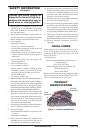
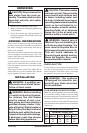
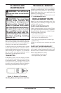
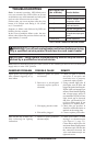
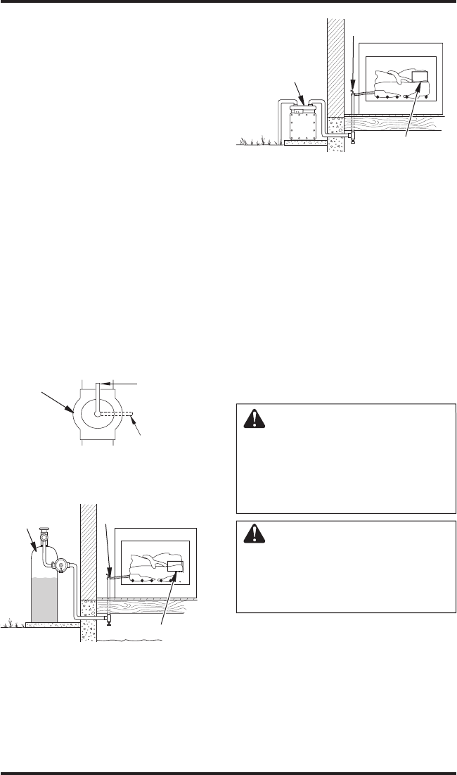
Figure 5 - Equipment Shutoff Valve
Equipment
Shutoff
Valve
Open
Closed
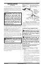
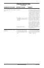
Figure 7 - Checking Gas Joints
(Natural Gas Only)
Control Valve
Location
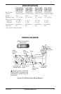
Equipment
Shutoff Valve
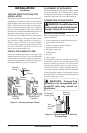
Propane/LP
Supply Tank
Equipment
Shutoff Valve
Gas Meter
Figure 6 - Checking Gas Joints
(Propane/LP Gas Only)
Control Valve
Location
4. Check all joints of gas supply piping system.
Apply noncorrosive leak detection fluid to all
joints. Bubbles forming show a leak.
5. Correct all leaks at once.
6. Reconnect heater and equipment shutoff
valve to gas supply. Check reconnected fit
-
tings for leaks.
Test Pressures Equal To or Less Than
1/2 PSIG (3.5 kPa)
1. Close equipment shutoff valve (see Figure 5).
2. Pressurize supply piping system by either
opening propane/LP supply tank valve for
propane/LP gas or opening main gas valve
located on or near gas meter for natural gas
or using compressed air.
3. Check all joints from gas meter to equipment
shutoff valve for natural gas or propane/LP
supply to equipment shutoff valve for propane/
LP (see Figure 6 or 7). Apply noncorrosive
leak detection fluid to all joints. Bubbles
forming show a leak.
4. Correct all leaks at once.
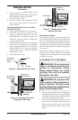
Gas Pressure Check
The appliance regulator controls the burner pres-
sure which should be checked at the pressure test
point (1/8" NPT plugged tap) located near the on
the control valve identified OUT for the manifold
side and IN for inlet pressure. Make sure operating
pressures are within the limits shown in Specifica-
tions, page 15.
The pressure should be checked with the unit
burning and set to High. Replace test point plug
or tighten test screw after pressure measurement
ensuring no gas leaks.
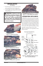
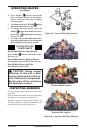
PLACEMENT OF FLOOR MEDIA
WARNING: Do not add extra
logs or ornaments such as pine
cones or vermiculite. Using
these added items can cause
sooting. Use only the material
included in the kits.
WARNING: Do not place lava
rock, embers or fiber log pieces on
logs or burners. This may cause
sooting. Place floor media material
only on the fireplace floor.
1. Place lava rock around base of unit making sure
the burner ports and valve access are not blocked
(see Figure 8, page 9). Retain a small amount of
lava rock to be used in step 4, page 9.
2. Place ember material around front and sides
of unit close to (but NOT on) the burner (see
Figure 9, page 9). Embers will "glow" when
heated to enhance the realistic look of your
log set.