www.desatech.com
115481-01B
6
PLACEMENT OF APPLIANCE
Center the appliance in the fireplace. Make certain
the grate front feet sit inside the front edge of
the fireplace and that there is adequate clearance
around the appliance for access and operation.
CONNECTING TO GAS SUPPLY
WARNING: A qualified service
person must connect heater to gas
supply. Follow all local codes.
Installation Items Needed
Before installing heater, make sure you have the
items listed below.
• external regulator (propane/LP models only)
• piping (check local codes)
• sealant (resistant to propane/LP gas)
• equipment shutoff valve
• test gauge connection
• sediment trap
• tee joint
• pipe wrench
For propane/LP units, the installer must supply
an external regulator. The external regulator will
reduce incoming gas pressure. You must reduce
incoming gas pressure to between 11 and 14 inches
of water. If you do not reduce incoming gas pres
-
sure, heater regulator damage could occur. Install
external regulator with the vent pointing down as
shown in Figure 3. Pointing the vent down protects
it from freezing rain or sleet.
WARNING: Connecting
directly to an unregulated pro
-
pane/LP tank may cause an
explosion.
Propane/LP
Supply Tank
External
Regulator
Vent
Pointing
Down
Figure 3 - External Regulator with Vent
Pointing Down
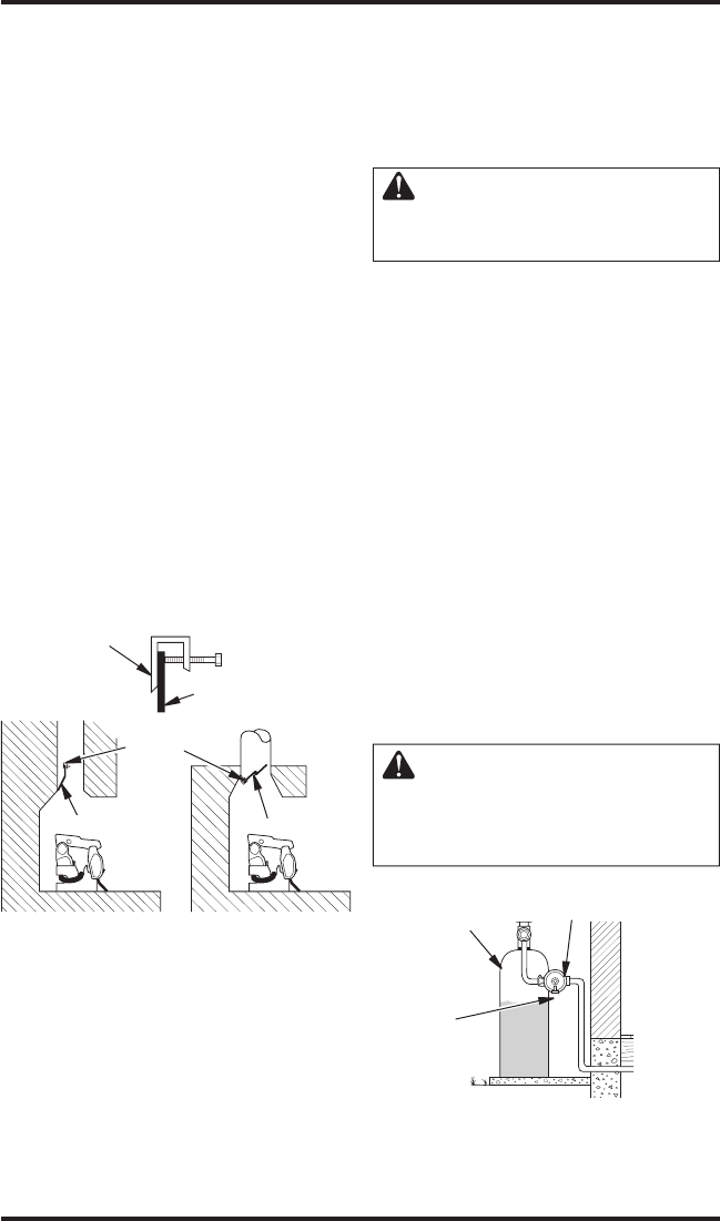
Figure 2 - Attaching Damper Clamp
Manufactured
Fireplace
Masonry
Fireplace
Damper
Damper
Clamp
Damper
Damper
Clamp
Damper
VENTING SPECIFICATIONS FOR
INSTALLATION
The fireplace chimney flue and vent must be draft-
ing properly. To check the vent for proper drafting:
Light a tightly rolled newspaper on one end and
place it at the inside front edge of the fireplace.
Observe the smoke and be sure the vent is properly
drawing it up the chimney. If the smoke spills out
into the room, extinguish the flame and remove any
obstruction until proper venting is achieved.
The chimney flue damper must be fixed open to
provide a minimum of 29 square inch flue opein
-
ing at all times during operation of the log set. A
damper clamp can be used to secure the damper
(see Accessories, page 18). See the National Fuel
Gas Code ANSI Z223.1/NFPA 54, Section 6.6 for
details about minimum flue size.
INSTALLING DAMPER CLAMP
Secure the damper stop clam to the edge of the
damper as shown in Figure 2. If for any reason this
clamp doesn't work on your fireplace, another suit-
able clamp or permanent stop must be iinstalled, or
the damper blade must be cut or removed.
INSTALLATION
Continued


