


www.desatech.com
118992-01L6
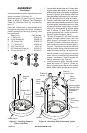
5. Remove wire tie and packing material
from regulator located underneath burner
support plate.
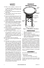
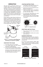
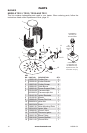
6. Position burner support plate on top of
panels while carefully inserting control
valve through hole in control panel.
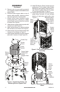
7. Attach control valve bracket to table
control panel with 2 screws (C). Attach
control knob to control valve from outside
of heater. See Figure 5.
8. Attach burner support plate to panels with
4 screws (C) (see Figure 5).
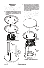
9.
Attach emitter screens to emitter brackets
with 4 screws (C) as shown in the Figure 5.
10. Attach emitter cap to emitter brackets with
2 screws (C) as shown in Figure 5.
11. Attach emitter assembly to burner support
plate with 2 screws (C) (see Figure 5).
ASSEMBLY
Continued
Burner
Support
Plate
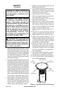
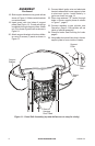
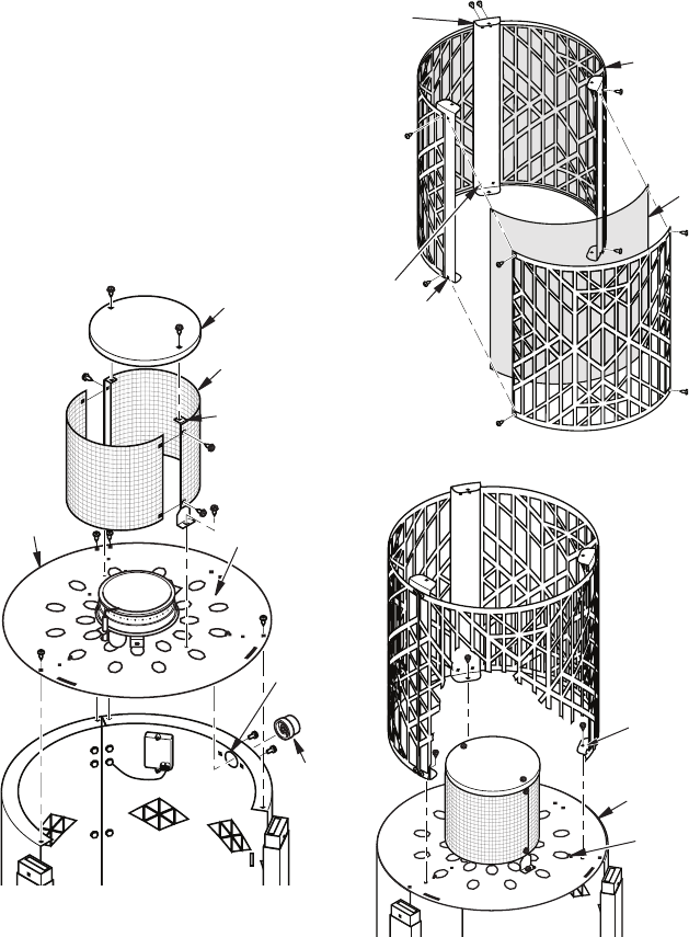
Figure 7 - Attaching Grate Assembly to
Heater
Screw
through
Deco
Grate
Pillar
Figure 6 - Deco Grate and Grate Pillar
Assembly
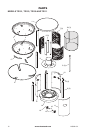
12. Model TD109 only: Place 3 screens around
grate pillars. For all models, place 3 table
decorative grate pieces around grate pil-
lars. Attach to grate pillars with 4 screws
(C) per grate as shown in Figure 6.
13.
Attach grate assembly to burner support
plate using 3 screws, (C) one through
bottom of each deco grate pillar (see
Figure 7).
Burner
Support
Plate
Hole for
Control
Valve
Control
Knob
Figure 5 - Assembling Emitter and
Attaching Burner Support Plate
Emitter Cap
Emitter
Screen
Emitter
Bracket
Control Valve
Underneath
Burner
Support Plate
Ring
Retainer
Screen
(Model
TD109
only)
Table Decorative
Grate (Models
TD101, TD103
and TD111
shown)
Deco
Grate
Pillar
(Holes
closest to
edge should
be on the
bottom)