


2. CR#1: The working mode of the 4 channels in the sensors selected by the temperature measurement module.
There are 2 modes (J-type and K-type) for each channel which can be set up separately. For example, if the
user needs to set up CH1: mode 0 (b2 ~ b0 = 100); CH2: mode 1 (b5 ~ b3 = 001); CH3: mode 0 (b8 ~ b6 =
000) and CH4: mode 1 (b11 ~ b9 = 001), CR#1 has to be set as H0208 and the higher bits (b12 ~ b15) have
to be reserved. The default value = H’0000.
3. CR#2 ~ CR#5: The times to average the temperatures measured at CH1 ~ CH4. Range: K1 ~ K20. Default =
K10. Please note that when PLC MPU writes in the average time by TO/DTO instruction, please use the
rising/falling edge contact detection instructions (LDP/LDF…) in case you may not obtain the correct average
temperature.
4. CR#6 ~ CR#9: The average Celsius temperature measured at CH1 ~ CH4 obtained from the average time
settings in CR#2 ~ CR#5. For example, if the average time is set as 10, the content in CR#6 ~ CR#9 will be
the average of the most recent 10 temperature signals in Celsius at CH1 ~ CH4.
5. CR#10 ~ CR#13: The average Fahrenheit temperature measured at CH1 ~ CH4 obtained from the average
time settings in CR#2 ~ CR#5. For example, if the average time is set as 10, the content in CR#10 ~ CR#13
will be the average of the most recent 10 temperature signals in Fahrenheit at CH1 ~ CH4.
6. CR #14 ~ CR #17: Displaying the present temperature in Celsius at CH1 ~ CH4
7. CR#18, CR#23, CR#28 and CR#29 are reserved.
8. CR #19 ~ CR #22: Displaying the present temperature in Fahrenheit at CH1 ~ CH4
9. CR #24 ~ CR #27: The adjusted OFFSET value of CH1 ~ CH4. Range: -1,000 ~ +1,000. Unit: 0.1°C.
Temperature measured by the module – OFFSET value = Actual temperature displayed.
10. CR #30: Error status (see the table below)
Error status Content b15 ~ b8
b7
b6
b5
b4
b3
b2
b1
b0
Abnormal power supply
K1(H’1) 0 0 0 0 0 0 0 1
Scale exceeds the range
or wiring to empty external
contact
K2(H’2) 0 0 0 0 0 0 1 0
Incorrect mode setting
K4(H’4) 0 0 0 0 0 1 0 0
OFFSET/GAIN error
K8(H’8) 0 0 0 0 1 0 0 0
Hardware malfunction
K16(H’10)
0 0 0 1 0 0 0 0
Abnormal digital range
K32(H’20)
0 0 1 0 0 0 0 0
Incorrect average times
setting
K64(H’40)
0 1 0 0 0 0 0 0
Instruction error
K128(H’80)
reserved
1 0 0 0 0 0 0 0
Note: Each error status is determined by the corresponding bit (b0 ~ b7) and there may be more than 2 errors occurring at the same time.
0 = normal; 1 = error
11. CR#31: The setting of RS-485 communication address. Range: 01 ~ 255. Default = K1.
12. CR#32: The setting of RS-485 communication speed. b0: 4,800bps; b1: 9,600bps (default); b2: 19,200bps; b3:
38,400bps; b4: 57,600bps; b5: 115,200bps; b6 ~ b13: reserved; b14: high/low bit exchange of CRC checksum
(only valid in RTU mode); b15: switching between ASCII mode and RTU mode.
13. CR#33: b0 ~ b11: For returning the CR settings to default settings.
b12 ~ b15: ERR LED definition. Default: b12 ~ b15 = 1111.
14. CR#34: Firmware version of the model.
15. CR#35 ~ CR#48: Parameters for system use.
16. CR#0 ~ CR#34: The corresponding parameter address H’4096 ~ H’40B8 are for users to read/write data by
RS-485 communication. When using RS-485, the user has to separate the module with MPU first.
a. Communication baud rate: 4,800/9,600/19,200/38,400/57,600/115,200 bps.
b. Modbus ASCII/RTU communication protocol: ASCII data format (7-bit, Even bit, 1 stop bit (7, E, 1));
RTU data format (8-bit, Even bit, 1 stop bit (8, E, 1)).
c. Function: H’03 (read register data); H’06 (write 1 word datum into register); H’10 (write many word data
into register).
d. Latched CR should be written by RS-485 communication to stay latched. CR will not be latched if written
by MPU through TO/DTO instruction.
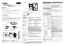
Temperature/Digital Curve
Temperature measurement modes
J-type thermocouple
+7,000(12,920)
-1,000(-1,480)
+700-100
C
C
F)
(-148
F)
(+1,292
Digital output
Measured
temperature input
K-type thermocouple
+10,000(18,320)
-1,000(-1,480)
+1,000-100
C
C
(-1,832 F)
Digital output
Measured
temperature input
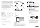
R & S-type thermocouple
+17,000(30,920)
-100(-140)
+1,700-10
C
C
F)
(-14
F)
(+3,092
Digital output
Measured
temperature input
T-type thermocouple
+3,500(6,620)
-1,000(-1,480)
+350
-100
C
C
F)
(-148
F)
(+662
Digital output
Measured
temperature input
Trial Operation & Troubleshooting
LED Display
1. When the module is powered for the first time, POWER LED will be on and ERROR LED will be on for
0.5 second. After this, A/D LED will start to flash.
2. When the power supply is normal, POWER LED will be on and ERROR LED should be off. When the
power supply is less than 19.5V, ERROR LED will keep being on until the power supply goes higher
than 19.5V.
3. When controlled by RS485, RS-485 LED on the module will flash after receiving the RS-485
instruction.
4. When the input or output value exceeds the upper bound or falls below the lower bound after
conversion, ERROR LED will flash.
Program Example
M1000
FROM K0
= H6403 D0
TO K0
FROM K0
FROM K0
FROM K0
FROM K0
END
M1002
K0
K2
K6
K10
K14
K19
D0
D10
D20
D24
D30
D34
K1
K4
K4
K4
K4
K4
Read the model name from K0 and see if it is DVP04TC-H2: H’6403
Set the average times in CH1 ~ CH4 as D10 ~ D13.
If D0 = H’6403, read the average temperature (°C) measured in CH1 ~ CH4 from CR#6 ~ CR#9 and store the
4 data in D20 ~ D23.
Read the average temperature (°F) measured in CH1 ~ CH4 from CR#10 ~ CR#13 and store the 4 data in
D24~ D27.
Read the average temperature (°C) measured in CH1 ~ CH4 from CR#14 ~ CR#17 and store the 4 data in
D30~ D33.
Read the average temperature (°F) measured in CH1 ~ CH4 from CR#19 ~ CR#22 and store the 4 data in
D34~ D37.
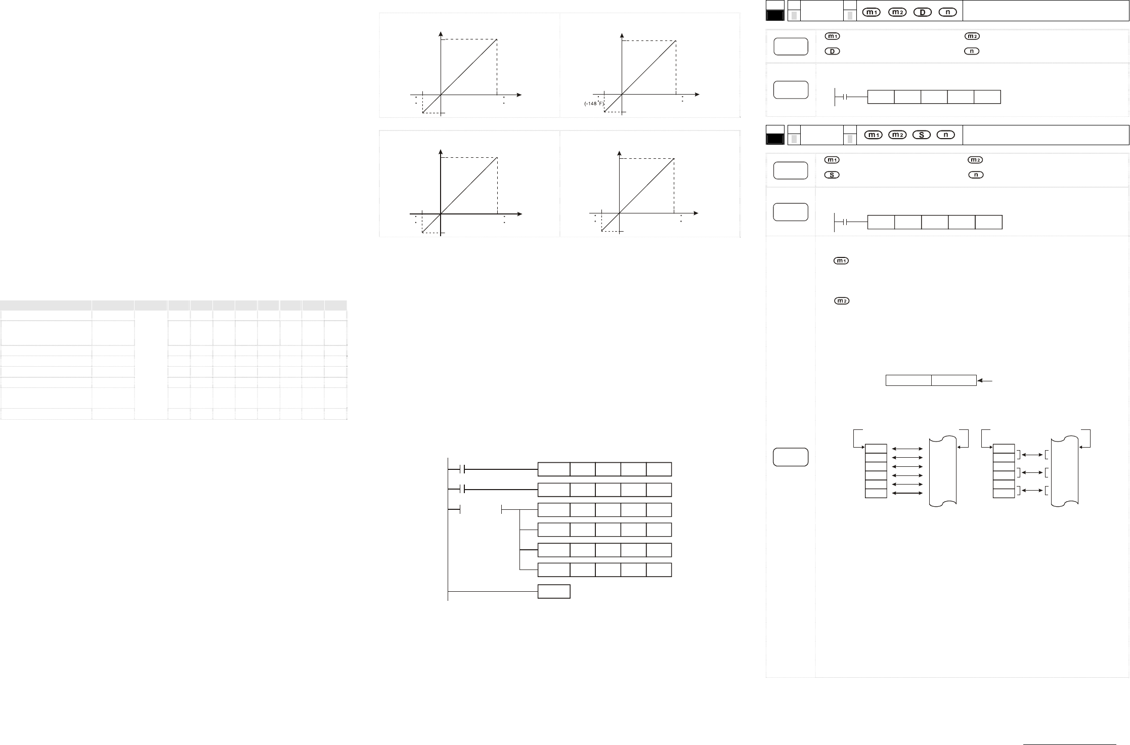
Relevant Instructions
API
78
D
FROM
P
Read CR data in special modules
Instruction
Explanation
: No. of special module (m1 = 0 ~ 7) : CR# in special module to be read
: Device for storing read data : Number of data to be read at a time
Program
Example
Read CR#24 of special module No. 0 into D0 and CR#25 into D1. Only 2 groups of data are
read at a time (n = 2).
X0
FROM K0 K24 D0 K2
API
79
D
TO
P
Write CR data into special module
Instruction
Explanation
: No. of special module (m1 = 0 ~ 7) : CR# in special module to be written
: Data to be written into CR : Number of data to be written at a time
Program
Example
Use 32-bit instruction DTO to write the content in D11 and D10 into CR#7 and CR#6 of special
module No. 0. Only 1 group of data is written in at a time (n = 1).
X0
DTO
K0 K6
D10
K1
Remarks
Operand rules
1.
: The No. of special modules connected to PLC MPU. No. 0 is the module closest to te
MPU. Maximum 8 modules are allowed to connected to a PLC MPU and they will not occupy
any I/O points.
2.
: CR#. CR (control register) is the 49 16-bit memories built in the special module,
numbered in decimal as #0 ~ #48. All operation status and settings of the special module are
contained in the CR.
3. FROM/TO instruction is for reading/writing 1 CR at a time. DFROM/DTO instruction is for
reading/writing 2 CRs at a time.
CR #10 CR #9
Lower 16-bit
Designated CR number
Higher 16-bit
4. Number of groups “n” to be transmitted: n = 2 in 16-bit instructions and n = 1 in 32-bit
instructions mean the same.
D0
D1
D2
D3
D4
D5
CR #5
CR #6
CR #7
CR #8
CR #9
CR #10
D0
D1
D2
D3
D4
D5
CR #5
CR #6
CR #7
CR #8
CR #9
CR #10
Designated device
Designated CR
Designated device
Designated CR
16-bit instruction when n=6
32-bit instruction when n=3
M1083 for switching instruction modes in EH2 series models
1. When M1083 = Off, during the execution of FROM/TO instruction, all external or internal
interruption subroutines will be forbidden. The interruptions are allowed only after FROM/TO
instruction finishes its execution. FROM/TO instruction can also be used in an interruption
subroutine.
2. When M1083 = On and an interruption signal occurs during the execution of FROM/TO
instruction, the interruption will be processed first (with a 100us delay) and the execution of
FROM/TO will be stopped. After the interruption subroutine finishes its execution, the
program will jump to the next instructio of FROM/TO. FROM/TO cannot be used in an
interruption subroutine.
The content of this instruction sheet may be revised without prior notice. Please consult our distributors or
download the most updated version at http://www.delta.com.tw/industrialautomation