


12 Section 4 — controlS & FeatureS
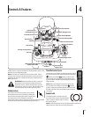
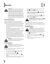
Forward Drive Pedal
The forward drive pedal is located on the right side
of the tractor, along the running board. Press the
drive pedal forward to cause the tractor to travel
forward. Ground speed is also controlled with
the drive pedal. The further forward the pedal is
pivoted, the faster the tractor will travel. The pedal
pressed.
Reverse Pedal
The reverse drive pedal is located on the right side of
the tractor along the running board. Ground speed
is also controlled with the reverse pedal. The further
downward the pedal is pivoted, the faster the tractor
will travel. The pedal will return to its original position
PTO/Blade Engage Lever
deck or other (separately available) attachments.
disengage the power to the cutting deck or other
(separately available) attachments.
NOTE:
engine.
Parking Brake/Cruise Control Lever
The parking brake/cruise control lever is located
to engage the parking brake when the tractor is
at rest. Engaging the lever while the tractor is in
motion allows the tractor to remain at a constant
ground speed without applying pressure to the
of this manual for detailed instructions regarding
the parking brake as well as the cruise control
feature.
NOTE:
to do so, the tractor will automatically decelerate to the fastest
optimal mowing ground speed
NOTE: The parking brake must be set if the operator leaves the
seat with the engine running or the engine will automatically
shut off.
WARNING! Never leave a running machine
brake, stop engine and remove key to prevent
unintended starting.
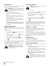
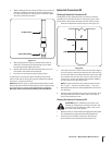
Manual Lift Lever (If so equipped)
LO
2
3
4
5
6
7
8
9
HI
The lift lever is located in the right fender and is used to raise
and lower the deck. Pull the handle to the left out of the index
notch and push downward to lower the deck, or pull upward to
raise the deck. When the desired height is attained, move the lift
handle to the right until fully in the index notch.
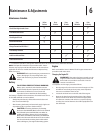
Electric Lift Switch (If so equipped)
ELECTRIC
DECK
LI
FT
RAISE
DECK
LOW
ER
DECK
To
Oper
ate
Electri
c Deck
Lift
Height
A
djustment
Raise
Electri
c Deck
Lift
To
The
Highe
st
Position.
Set
Cutting
Height.
Lower
Electri
c Deck
Lift
To
Chosen
Cutting
Position.
The electric lift switch located in the right fender and is used to
raise and lower the deck. To lower the deck press down on the
front of the switch and to raise the deck push down on the rear of
the switch.
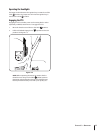
Cutting Height Lever (If so equipped)
LO 1 2 3 4 5 HI
The cutting height lever is used to set the distance the deck can
be lowered. The cutting height lever can be set to six different
positions by moving the lever up or down to the desired setting.
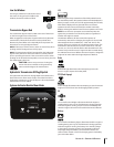
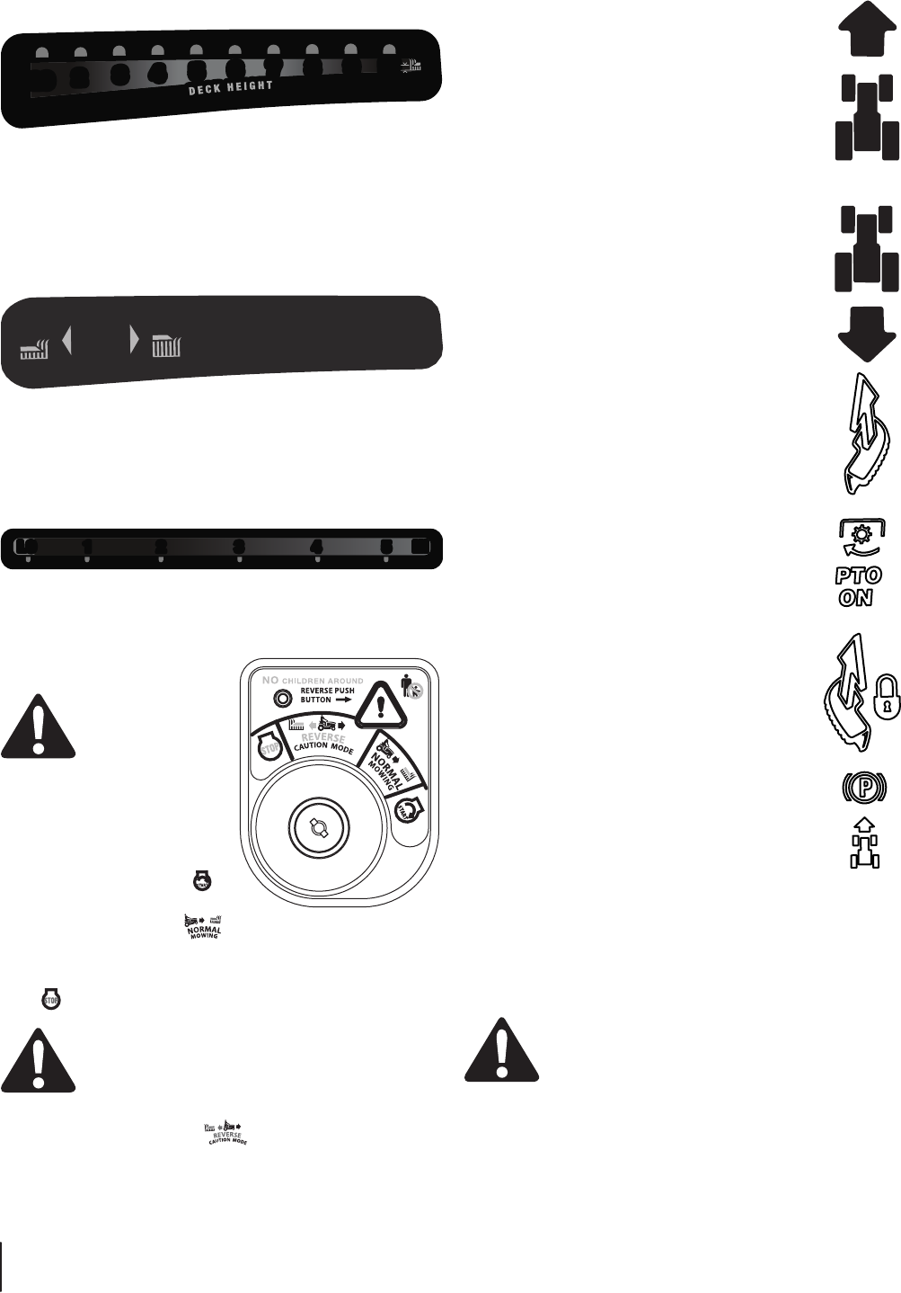
Ignition Switch Module
WARNING! Never
leave a running
machine unattended.
Always disengage
engine and remove key to prevent
unintended starting.
To start the engine, insert the
key into the ignition switch and
turn clockwise to the START
position. Release the key into the
position once the engine has
fired.
To stop the engine, turn the ignition key counterclockwise to the
position.
CAUTION: Prior to operating the tractor, refer to
both Safety Interlock Switches and Starting The
detailed instructions regarding the Ignition Switch
Module and operating the tractor in REVERSE
.