


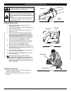
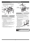
• If using a torque wrench and a
13 mm socket tighten to: 325 -
335 in•lb, 27 - 28 ft.•lb, 37 - 38
N•m.
• Without a torque wrench, use a
13 mm closed-end or socket
wrench, turning the nut until the
blade retainer is snug against
the shaft bushing. Make sure
that the blade is installed
correctly, then rotate the nut
an additional 1/4 to 1/2 turn
counterclockwise (Fig. 12).
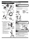
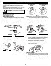
9. Remove the locking rod
from the locking rod slot.
Remove the Cutting Attachment
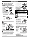
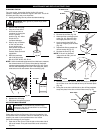
1. Align the shaft
bushing hole
with the locking
rod slot and
insert the locking
rod into the shaft
bushing hole
(Fig. 7).
2. Hold the locking
rod in place by
grasping it next
to the boom of the unit (Fig. 8).
3. While holding the locking rod,
remove the cutting attachment
by turning it clockwise off of the
output shaft (Fig. 9). Store the
cutting attachment for future use.
NOTE: The blade retainer under the
cutting attachment will be
used when installing the cutting blade.
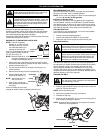
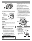
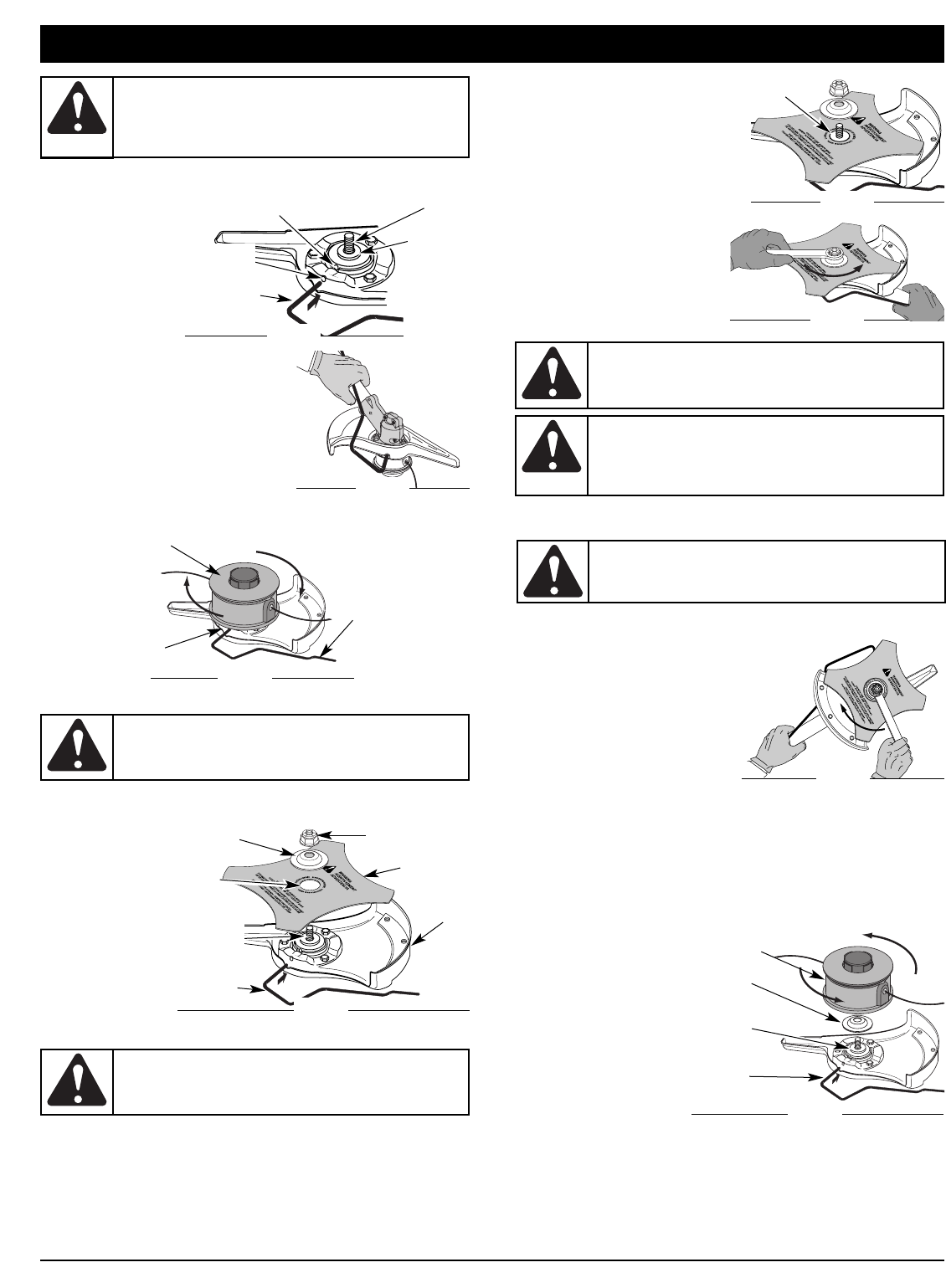
Install the Cutting Blade
4. Place the
cutting blade
on the output
shaft bushing
(Fig. 10).
5. Make sure that
the cutting
blade is
centered on the
pilot step and
sitting flat
against the
output shaft
bushing (Fig. 10).
6. Align the shaft bushing hole with the locking rod slot and
insert the locking rod into the bushing hole (Fig. 7).
7. Put the blade retainer and nut on the output shaft. Make
sure that the blade is installed correctly.
8. Tighten nut counterclockwise against the blade while
holding the locking rod:
5
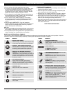
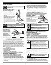
WARNING: The gear housing gets hot with use. It can
result in injury to the operator. The housing remains
hot for a short time even after the unit is turned off. Do
not touch the gear housing until it has cooled.
WARNING: To avoid serious personal injury,
always wear gloves while handling or installing the
blade.
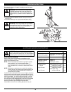
WARNING: If the cutting blade is off-center, the
unit will vibrate and the blade may fly off, causing
possible serious personal injury.
WARNING: To avoid serious personal injury or
damage to the unit, do not start or operate this unit
with the locking rod in the locking rod slot.
WARNING: Do not sharpen the cutting blade.
Sharpening the blade can cause the blade tip to
break off while in use. This can result in severe
personal injury. Replace the blade.
Shaft Bushing
Hole
Locking
Rod
Output Shaft
Fig. 7
Output
Shaft
Bushing
Locking
Rod Slot
Fig. 8
Cutting
Attachment
Locking
Rod Slot
Locking
Rod
Fig. 9
Pilot Step
Fig. 11
Shield
Mount
Locking
Rod
Cutting
Blade
Blade
Retainer
Nut
Pilot
Hole
Fig. 10
Output
Shaft
Bushing
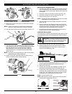
ASSEMBLY INSTRUCTIONS
REMOVE THE CUTTING BLADE AND INSTALL THE CUTTING
ATTACHMENT
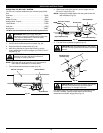
Remove the Cutting Blade
1. Align the shaft bushing hole
with the locking rod slot and
insert the locking rod into the
bushing hole (Fig. 7).
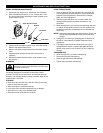
2. Hold the locking rod in place
by grasping it next to the
boom of the unit (Fig. 13).
3. While holding the locking
rod, loosen the nut on the
blade by turning it clockwise
with a 13 mm closed-end or socket wrench (Fig. 13).
4. Remove the nut, blade retainer and blade. Store the nut
and blade together for future use in a secure place. Store
out of children’s reach.
Install the Cutting Attachment
5. Align the shaft bushing hole with the locking rod slot and
insert the locking rod into the shaft bushing hole (Fig. 7).
Place the blade
retainer on the
output shaft with the
flat surface against
the output shaft
bushing (Fig. 14).
Screw the cutting
attachment
counterclockwise
onto the output
shaft. Tighten
securely.
NOTE: The blade retainer must be installed on the output shaft
in the position shown for the cutting attachment to
work correctly.
6. Remove the locking rod.
7. Install the cutting attachment shield. Refer to Remove and
Install the Cutting Attachment Shield.
Clockwise
Fig. 13
Cutting Attachment
Locking
Rod
Blade
Retainer
Output
Shaft
Bushing
Fig. 14
WARNING: To avoid serious personal injury,
always wear gloves while handling or installing the
blade.
Fig. 12