


10
WARNING: The temperature of the muffler
and the surrounding areas may exceed
150
°
F. Avoid these areas.
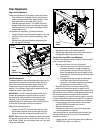
• For the most efficient snow removal, remove snow
immediately after it falls.
• Discharge the snow downwind whenever possible.
• Slightly overlap each previous path.
• Set the skid shoes 1/4" below the shave plate for
normal usage. The skid shoes may be adjusted
upward (to lower the shave plate) for hard-packed
snow. Adjust downward (to raise the shave plate)
when using on gravel or crushed rock.
SECTION 5: MAKING ADJUSTMENTS
WARNING: NEVER attempt to make any
adjustments while the engine is running,
except where specified in the operator’s
manual.
Chute Assembly Adjustment
The distance snow is thrown can be adjusted by
adjusting the angle of the chute assembly. Refer to the
Chute Tilt Control in the Know Your Snow Thrower
Section.
Traction Control Adjustment
Refer to the information found under Final Adjustment
in the Assembly Section to adjust the traction control. If
you are uncertain that you have reached the correct
adjustment, proceed as follows:
WARNING: Drain the gasoline out of the
snow thrower’s tank, or place a piece of
plastic film under the gas cap to avoid
spillage BEFORE making the adjustment.
• Tip the snow thrower forward, allowing it to rest on
the auger housing.
• Remove the frame cover underneath the snow
thrower by removing the six self-tapping screws.
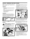
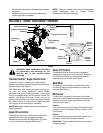
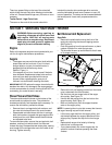
• With the traction control released, there must be
clearance between the friction wheel and the drive
plate in all positions of the shift lever.
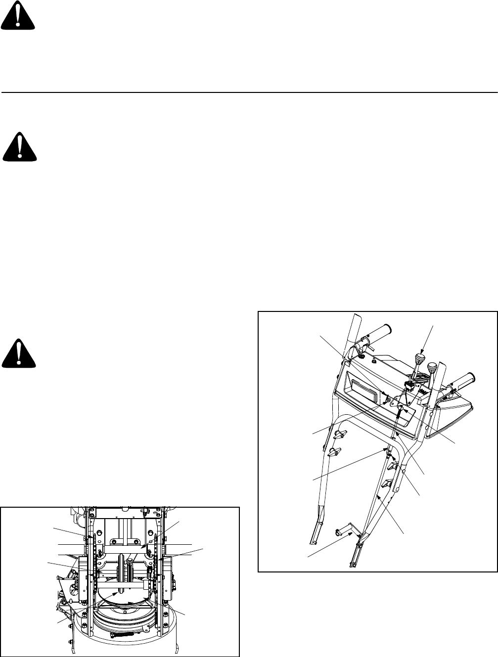
• With the traction control engaged, the friction wheel
must contact the drive plate. See Figure 8.
Figure 8
If adjustment is necessary:
• Loosen the jam nut on the traction drive cable and
adjust the cable as necessary. Refer to Figure 5.
• Retighten the jam nut to secure the cable when
correct adjustment is reached.
• Reassemble the frame cover.
NOTE: If you placed plastic film under the gas cap, be
certain to remove it before operating the snow thrower.
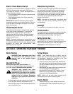
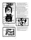
Shift Rod Adjustment
To adjust the shift rod, proceed as follows:
• Remove the hairpin clip and slide the shift rod
connector up, to separate the upper shift rod from
the lower shift rod. See Figure 9.
Figure 9
• Place the shift lever into the sixth (6) position.
• Rotate the shift arm clockwise (from the operator’s
position) as far as it will go.
• Thread the upper shift rod downward until the
elbow on its lower end aligns with the hole found in
the lower shift rod.
Axle Shaft
Chain
Drive Plate
Friction
Wheel
Gear
Shaft
Sprocket
Shift Lever
Ferrule
Shift Arm
Hairpin
Clip
Lower Shift Rod
Clutch Rod
Upper Shift Rod
Connector
Hairpin Clip
Flat
Washer