


GROUND SPEED CONTROL LEVER
ADJUSTMENT
The control levers have three adjustments:
To Adjust Control Lever Height: Pull the levers in
across the operator's lap to their DRIVE positions.
Loosen the mount bolts (D, Figure 34) and raise or lower
the levers to the desired position. Tighten the mounting
bolts.
To Adjust Control Lever End Gap: The control lever
end gap should be adjusted so that the levers do not
contact each other when placed in DRIVE positions.
Loosen the jam nut (A, Figure 34) and adjust the length
of the carriage bolt (B) so that the levers do not contact
each other. Repeat on the opposite side. Tighten the jam
nut (A) to lock the carriage bolt in position.
To Adjust Operator Clearance: The space between the
operator and the control levers can be increase by
removing the lower mounting bolt (D, Figure 34), pivoting
the lever forward, and reinstalling the capscrew through
the control lever and forward slot (C). Repeat with the
other ground speed lever.
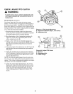
SPEED BALANCING ADJUSTMENT
If the rider veers to the right or left when the ground
speed control levers are in the maximum forward posi-
tion, the top speed of the right lever can be balanced by
turning the adjustment knob (E, Figure 34). Loosen the
jam nut and turn the knob COUNTERCLOCKWISE to
increase speed or CLOCKWISE to decrease speed.
Tighten the jam nut when complete.
\
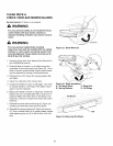
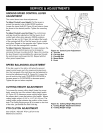
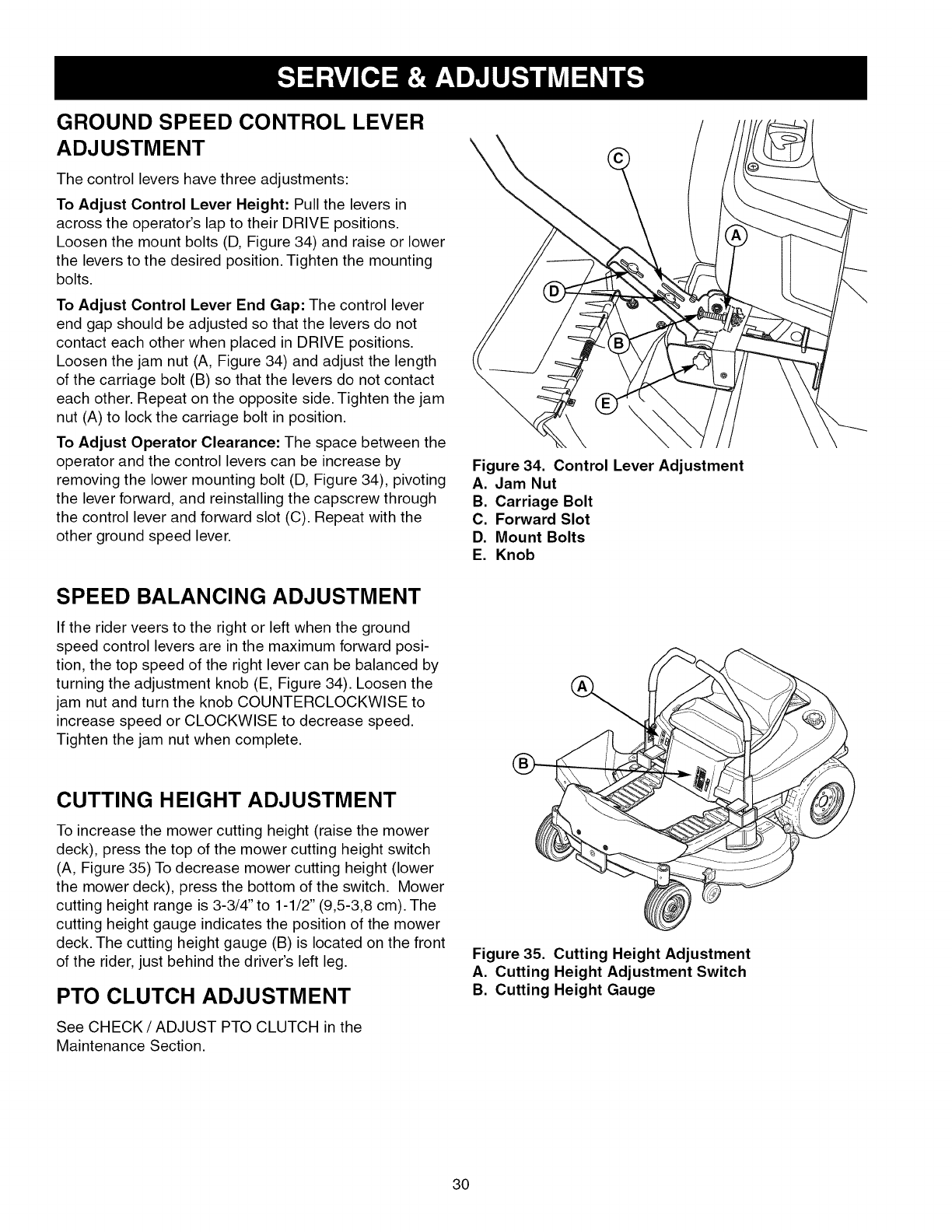
Figure 34. Control Lever Adjustment
A. Jam Nut
B. Carriage Bolt
C. Forward Slot
D. Mount Bolts
E. Knob
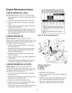
CUTTING HEIGHT ADJUSTMENT
To increase the mower cutting height (raise the mower
deck), press the top of the mower cutting height switch
(A, Figure 35) To decrease mower cutting height (lower
the mower deck), press the bottom of the switch. Mower
cutting height range is 3-3/4" to 1-1/2" (9,5-3,8 cm). The
cutting height gauge indicates the position of the mower
deck. The cutting height gauge (B) is located on the front
of the rider, just behind the driver's left leg.
PTO CLUTCH ADJUSTMENT
See CHECK / ADJUST PTO CLUTCH in the
Maintenance Section.
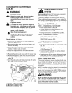
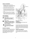
Figure 35. Cutting Height Adjustment
A. Cutting Height Adjustment Switch
B. Cutting Height Gauge
30