


STANDARDS: This edger attachment is Listed by Underwriter's Laboratories,
Inc., in accordance with UL Standard 1602, "Gasoline- Engine- Powered, Rigid-
Cutting-Member Edgers and Edger Trimmers," only when used with the following
models:
25cc Powerhead (with trimmer attachment) ..................... 944.51556
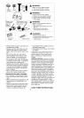
CARTON CONTENTS
Check carton contents against the fol-
lowing list.
Model C944.511573
• Edger attachment
• Handlebar
• Handlebar mounting bracket for 1"
(2.5 cm) shaft
• Handlebar mounting bracket for 7/8"
(2.2 cm) shaft
• Bracket cover (2)
• Handlebar bracket screws (4)
• Attachment Hanger
• Hex Wrench
Examine parts for damage. Do not
use damaged parts.
NOTE: If you need assistance or find
parts missing or damaged, contact
your Sears Service Centre.
ASSEMBLY
_,WARNING: If received as-
sembled, repeat all steps to ensure
your unit is properly assembled and all
fasteners are secure.
• A hex wrench (provided) is required
for assembly.
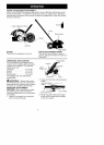
HANDLEBAR ASSEMBLY
_DANGER: RISKOFCUT. To
avoid serious injury, the barrier portion
of the handlebar must be installed as
shown on the upper shaft of the pow-
erhead to provide a barrier between
operator and the spinning blade. At-
tach handlebar mounting bracket
above arrow on safety warning decal
on the upper shaft (powerhead end of
unit). Ensure handlebar is positioned
on mounting bracket at the end of the
arrow on the handlebar decal.
NOTE: Two mounting brackets are in-
cluded with this attachment. Both brack-
ets are provided to adapt this attach-
ment for use with powerheads that have
either a 1" (2.5 cm) diameter or a 7/8"
(2.2 cm) diameter upper shaft. The cor-
rect bracket must be used to ensure
that the handlebar is mounted securely
to the upper shaft before use.
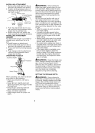
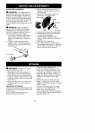
Bracket Cover
Mountinc
Bracket /
i
1. Place the mounting bracket over
the upper shaft above the arrow on
the safety label. Be sure to use the
correct mounting bracket for either
the 1" (2.5 cm) or 7/8" (2.2 cm) di-
ameter upper shaft.
2. Position one of the bracket covers
under the upper shaft and align the
mounting bracket and the bracket
cover screw holes. Insert two
screws into the screw holes.
3. Secure the mounting bracket by
tightening the screws with the hex
wrench.
4. Locate the decal on the handlebar.
This decal includes an arrow. Posi-
tion the handlebar with the mount-
ing bracket at the end of the arrow.
5. Position the second bracket cover
over the handlebar. Align the
mounting bracket and the bracket
cover screw holes. Again make
sure the handlebar is at the end of
the arrow.
6. Insert two screws and hand tighten
only. Be sure the handlebar is
installed correctly; then, tighten
each screw securely with the hex
wrench.
NOTE: Adjustments can be made by
loosening the bracket cover screws
and moving the mounting bracket or
handlebar up or down the shaft. Be
sure the handlebar is installed correct-
ly; then, retighten each screw securely
with the hex wrench.