


8. Raise attachment lift to its highest posi-
tion.
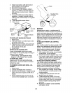
9. Slide mower forward and remove belt
from electric clutch pulley.
10. Slide mower out from under right side
of tractor.
TO INSTALL MOWER
Be sure tractor is on level surface and
mower suspension arms are raised with
attachment lift control. Engage parking
brake.
1. Swing anti-sway bar to left side of
mower deck.
2. Slide mower under tractor with deflec-
tor shield to right side of tractor.
IMPORTANT: Check belt for proper rout-
ing in all mower pulley grooves.
3. If equipped, turn height adjustment
knob counterclockwise until it stops.
4. Lower mower linkage with attachment
lift control.
5. Be sure belt tension rod is in disen-
gaged position.
6. Install belt into electric clutch pulley
groove.
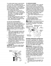
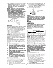
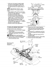
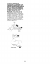
7. Place the suspension arms on outward
pointing deck pins. Retain with double
loop retainer spring with loops up as
shown.
8. Install front plate assembly to tractor
suspension brackets and retain with
single loop retainer springs as shown.
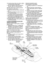
9. Position front plate assembly between
front mower brackets. Raise deck and
plate assembly to align holes and
insert flanged pins. Secure pins with
double loop retainer springs between
the plate assembly and mower brack-
ets.
NOTE: To assist in locating hole in flanged
pin, the hole in pin is inline with notch on
head of pin. If necessary, move mower
side-to-side to give space between plate
and mower brackets.
IMPORTANT: Check belt for proper rout-
ing in all mower pulley grooves.
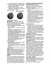
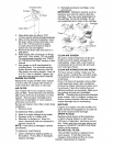
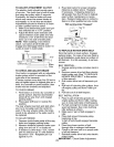
10. Engage belt tension rod by pushing rod
into locking bracket.
A CAUTION: Belt tension rod is spring
loaded. Have a tight grip on rod and en-
gage slowly.
11. Connect anti-sway bar to chassis
bracket under left footrest and retain
with double loop retainer spring.
12. If equipped, turn height adjustment
knob clockwise to remove slack from
mower suspension.
13. Raise deck to highest position.
TO LEVEL MOWER HOUSING
Adjust the mower while tractor is parked
on level ground or driveway. Make sure
tires are properly inflated (See "PROD-
UCT SPECIFICATIONS" section of this
manual). If tires are over or underinflated,
you will not properly adjust your mower.
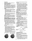
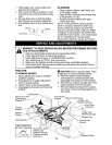
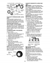
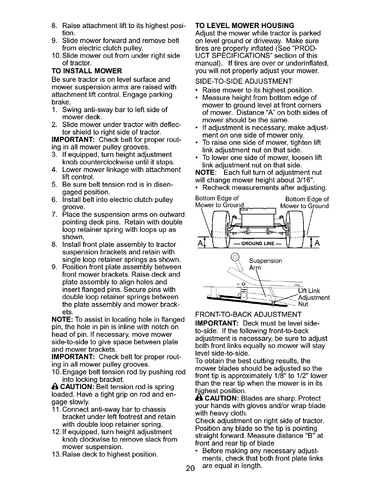
SIDE-TO-SIDE ADJUSTMENT
• Raise mower to its highest position.
• Measure height from bottom edge of
mower to ground level at front corners
of mower. Distance "A" on both sides of
mower should be the same.
• If adjustment is necessary, make adjust-
ment on one side of mower only.
• To raise one side of mower, tighten lift
link adjustment nut on that side.
• To lower one side of mower, loosen lift
link adjustment nut on that side.
NOTE: Each full turn of adjustment nut
will change mower height about 3/16".
• Recheck measurements after adjusting.
Bottom Edge of Bottom Edge of
owe oirou
_Ar_ Suspensi°n
uok
_Adjustment
_Nut
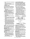
FRONT-TO-BACK ADJUSTMENT
IMPORTANT: Deck must be level side-
to-side. If the following front-to-back
adjustment is necessary, be sure to adjust
both front links equally so mower will stay
level side-to-side.
To obtain the best cutting results, the
mower blades should be adjusted so the
front tip is approximately 1/8" to 1/2" lower
than the rear tip when the mower is in its
_hest position.
CAUTION: Blades are sharp. Protect
your hands with gloves and/or wrap blade
with heavy cloth.
Check adjustment on right side of tractor.
Position any blade so the tip is pointing
straight forward. Measure distance "B" at
front and rear tip of blade
• Before making any necessary adjust-
ments, check that both front plate links
20 are equal in length.