


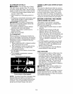
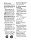
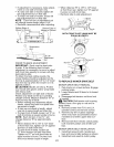

• If adjustment is necessary, make adjust-
ment on one side of mower only.
• To raise one side of mower, tighten lift
link adjustment nut on that side.
• To lower one side of mower, loosen lift
link adjustment nut on that side.
NOTE: Each full turn of adjustment nut
will change mower height about 3/16".
• Recheck measurements after adjusting.
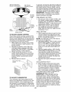
Bottom Edge of Bottom Edge of
Mower to Ground Mower to Ground
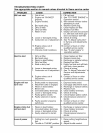
Suspension
-- ____\_ ........ _ift Link
Adjustment
_-_- Nut
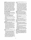
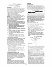
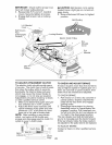
FRONT-TO-BACK ADJUSTMENT
IMPORTANT: Deck must be level side-
to-side. If the following front-to-back
adjustment is necessary, be sure to adjust
both front links equally so mower will stay
level side-to-side.
To obtain the best cutting results, the
mower blades should be adjusted so the
front tip is approximately 1/8" to 1/2" lower
than the rear tip when the mower is in its
ghest position.
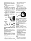
CAUTION: Blades are sharp. Protect
your hands with gloves and/or wrap blade
with heavy cloth.
Check adjustment on right side of tractor.
Position any blade so the tip is pointing
straight forward. Measure distance "B" at
front and rear tip of blade
• Before making any necessary adjust-
ments, check that both front plate links
are equal in length.
• If links are not equal in length, adjust
one link to same length as other link.
• To lower front of blade, loosen nut "C" on
both front links an equal number of turns.
NOTE: Each full turn of nut "C" will
change distance "B" by approximately
3/16".
• When distance "B" is 1/8" to 1/2" lower
at front than rear, tighten nut "D" against
trunnion on both front links.
• To raise front of blade, loosen nut
"D" from trunnion on both front links.
Tighten nut "C" on both front links an
equal number of turns. The two front
links must remain equal in length.
When distance "B" is 1/8" to 1/2" lower
at front than rear, tighten nut "D" against
trunnion on both front links.
Recheck side-to-side adjustment.
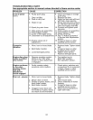
_°o\_ I oo/ Blade
BOTH FRONT PLATE LINKS MUST BE
EQUAL IN LENGTH
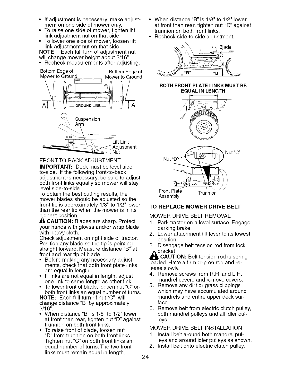
Front Plate
Assembly
Trunnion
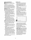
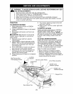
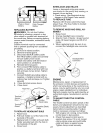
TO REPLACE MOWER DRIVE BELT
MOWER DRIVE BELT REMOVAL
1. Park tractor on a level surface. Engage
parking brake.
2. Lower attachment lift lever to its lowest
position.
3. Disengage belt tension rod from lock
bracket.
CAUTION: Belt tension rod is spring
loaded. Have a firm grip on rod and re-
lease slowly.
4. Remove screws from R.H. and L.H.
mandrel covers and remove covers.
5. Remove any dirt or grass clippings
which may have accumulated around
mandrels and entire upper deck sur-
face.
6. Remove belt from electric clutch pulley,
both mandrel pulleys and all idler pul-
leys.
MOWER DRIVE BELT INSTALLATION
1. Install belt around both mandrel pul-
leys and around idler pulleys as shown.
2. Install belt onto electric clutch pulley.
24