


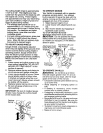
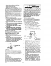
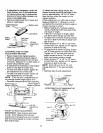
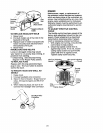
• If adjustment is necessary, under left
hand footrest, turn lift link adjustment
nut (above yellow cap) in appropriate
direction to bring bubble between the
lines in the bubble level.
• Remove bubble level from mower and
store in a safe place.
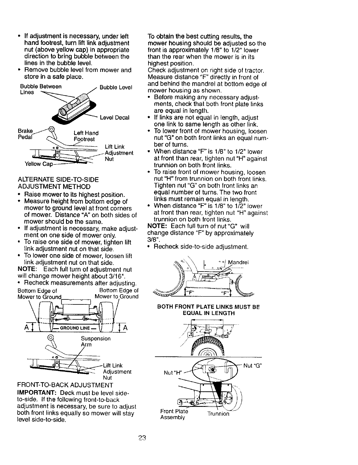
Bubble Between Bubble Level
Lines
Level Decal
pBerake_ Left Hand
o_--_____. Lift Link
,_ L-__ _Adjustment
"_ Nut
Yellow Cap__
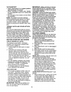
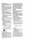
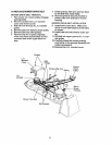
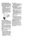
ALTERNATE SIDE-TO-SIDE
ADJUSTMENT METHOD
• Raise mower to its highest position.
• Measure height from bottom edge of
mower to ground level at front corners
of mower. Distance "A" on both sides of
mower should be the same.
• If adjustment is necessary, make adjust-
ment on one side of mower only.
• To raise one side of mower, tighten lift
link adjustment nut on that side.
• To lower one side of mower, loosen lift
link adjustment nut on that side.
NOTE: Each full turn of adjustment nut
will change mower height about 3/16".
• Recheck measurements after adjusting.
Bottom Edge of Bottom Edge of
Mower to Ground Mower to.Ground
Suspension
_Lif_L_tken t
Nut
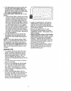
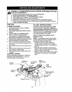
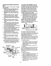
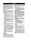
FRONT-TO-BACK ADJ USTM ENT
IMPORTANT: Deck must be level side-
to-side. If the following front-to-back
adjustment is necessary, be sure to adjust
both front links equally so mower will stay
level side-to-side.
To obtain the best cutting results, the
mower housing should be adjusted so the
front is approximately 1/8" to 1/2" lower
than the rear when the mower is in its
highest position.
Check adjustment on right side of tractor.
Measure distance "F" directly in front of
and behind the mandrel at bottom edge of
mower housing as shown.
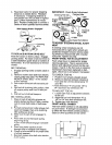
• Before making any necessary adjust-
ments, check that both front plate links
are equal in length.
• If links are not equal in length, adjust
one link to same length as other link.
• To lower front of mower housing, loosen
nut "G" on both front links an equal num-
ber of turns.
• When distance "F" is 1/8" to 1/2" lower
at front than rear, tighten nut "H" against
trunnion on both front links.
• To raise front of mower housing, loosen
nut "H" from trunnion on both front links.
Tighten nut "G" on both front links an
equal number of turns. The two front
links must remain equal in length.
• When distance "F" is 1/8" to 1/2" lower
at front than rear, tighten nut "H" against
trunnion on both front links.
NOTE: Each full turn of nut"G" will
change distance "F" by approximately
3/8".
• Recheck side-to-side adjustment.
andrel
_F t ,
BOTH FRONT PLATE LINKS MUST BE
EQUAL IN LENGTH
Nut
Front Plate Trunnion
Assembly
23