


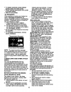
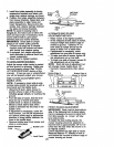
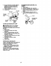
7. Install front plate assembly to tractor
suspension brackets and retain with
single loop retainer springs as shown.
8. Position front plate assembly between
front mower brackets. Raise deck and
plate assembly to align holes and
insert flanged pins. Secure pins with
double loop retainer springs between
the plate and mower brackets.
NOTE: To assist in locating hole in
flanged pin, the hole in pin is inline with
notch on head of pin. If necessary, move
mower side-to-side to give space
between plate and mower brackets.
IMPORTANT: Check belt for proper
routing in all mower pulley grooves.
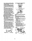
9. Connect anti-sway bar to chassis
bracket under left footrest and retain
with double loop retainer spring.
10. If equipped, turn height adjustment
knob clockwise to remove slack from
mower suspension.
11. Raise deck to highest position.
TO LEVEL MOWER HOUSING
Adjust the mower while tractor is parked
on level ground or driveway. Make sure
tires are properly inflated (See =PROD-
UCT SPECIFICATIONS" section of this
manual). If tires are over or underinflated,
you will not properly adjust your mower.
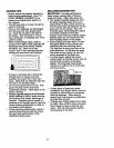
SIDE-TO-SIDE ADJUSTMENT WITH
BUBBLE LEVEL
NOTE: If necessary, check side-to-side
surface below tractor for levelness with a
long board and the bubble level.
• Using the lift lever, place mower in
position where no part of the mower,
including gauge wheels, is touching the
ground.
• From left side of tractor, find the level
decal on top of mower and place
bubble level on decal as indicated.
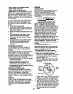
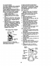
• Mower is level side-to-side when
bubble is between the two lines in the
bubble level.
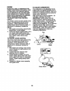
• If adjustment is necessary, under left
hand footrest, turn lift link adjustment
nut (above yellow cap) in appropriate
direction to bring bubble between the
lines in the bubble level.
• Remove bubble level from mower and
store in a safe place.
Bubble Between . Bubble Level
__ _ Level Decal
Lines
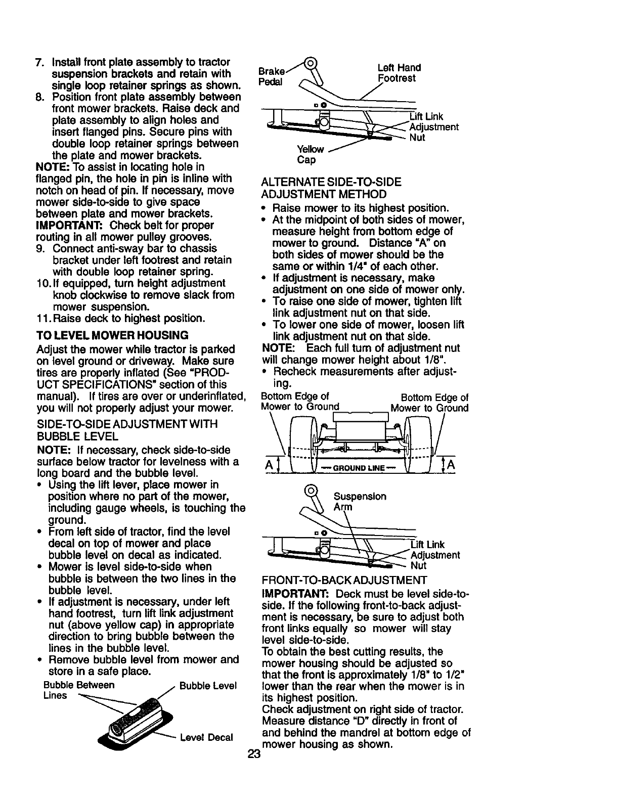
Brake.,,_ Left Hand
Pedal _ jootrest
LiftUnk
Adjustment
Nut
Cap
ALTERNATE SIDE-TO-SIDE
ADJUSTMENT METHOD
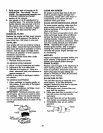
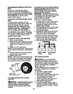
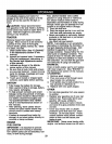
• Raise mower to its highest position.
• At the midpoint of both sides of mower,
measure height from bottom edge of
mower to ground. Distance =A" on
both sides of mower should be the
same or within 1/4" of each other.
• If adjustment is necessary, make
adjustment on one side of mower only.
• To raise one side of mower, tighten lift
link adjustment nut on that side.
• To lower one side of mower, loosen lift
link adjustment nut on that side.
NOTE: Each full turn of adjustment nut
will change mower height about 1/8".
• Recheck measurements after adjust-
ing.
Bottom Edge of Bottom Edge of
Mower to Ground Mower to Ground
=o_ Suspensi°n
_Adjuslmenl
__ Nut
FRONT-TO-BACK ADJUSTMENT
IMPORTANT: Deck must be level side-to-
side. If the following front-to-back adjust-
ment is necessary, be sure to adjust both
front links equally so mower will stay
level side-to-side.
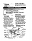
To obtain the best cutting results, the
mower housing should be adjusted so
that the front is approximately 1/8" to 1/2"
lower than the rear when the mower is in
its highest position.
Check adjustment on right side of tractor.
Measure distance "D" directly in front of
and behind the mandrel at bottom edge of
mower housing as shown.
23