


•
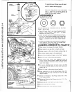
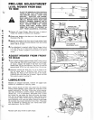
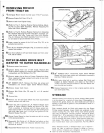
REMOVING MOWER
FROM TRACTOR
1.
Disengage Mower Clutch
Control
Lever
("ouT"
position).
2.
Remove Engine Belt
Guard
(Fig.
4).
3
.Remove
belt
from
Engine Pulley.
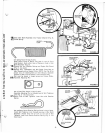
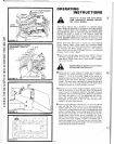
4.
(Refer
to
Fig. 7). Remove Retainer Spring holding
Adjust
·
ing Pin
to
I
dler
Shaft
Assembly. Remove Adjusting Pin
from
Idl
er
Shaft
Assembly.
5.
(Refer
to
Fig.
8).
Remove
Retainer
Spring
from
Adjusting
Pin. Remove Adjusting
Pin fr
om
Idler
Sha
ft
Assembly. Un-
hook
Spring
from
Idler
Frame
and
Front
Axle Bracket.
(Fig.
5).
Remove Idler
Shaft
Assembly
from
front
of
trac·
tor
and
place
on
ground
between
front
wheels.
6.
Lower
mower
by means
of
the
Lift Lever (Fig. 12),
to
its
extreme
low
position.
7. Pull all
four
Attaching
Plungers (Fig. 2)
outward
to
detach
mower
from
tractor.
B.
Turn
fr
ont
wheels
to
left
and
slide
mower
out
from
under
R .H. side
of
tractor
.
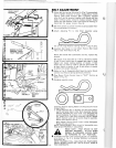
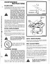
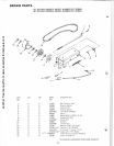
OUTER BLADES DRIVE
BELT
ICENTER
TO
OUTER
MANDRELSJ
1. Remove
mower
from
tractor.
2 .
Unhook
Spring
from
rear
of
Belt
Guide.
Remove
Belt
Guide
at
center
mandrel by removing
the
3 Belt Guide Nuts,
Lockwashers,
and
Flat
Washers (Fig. 19).
3.
Remove
cotter
pins
at
front
of
Lower Suspension
Arms.
Move suspension linkage
outward
and
swing
to
rear--both
R.H.
and
L.H. sides.
4.
48"
MOW
ER
ONLY.
Remove the
three
cap
screws
and
lockwashers
and
remove Upper
Center
Mandrel Sheave.
5.
Remove mower
deck
Cover.
&.
Remove Belt
Guide
(No.
26
, page 10,
at
L.H. mandrel
sheave.
7. Remove Belt.
B.
Remove any
dirt
and
grass
which
may have
accumulated
around
sheaves
and
idler
arm.
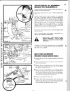
9.
1nstall new belt in groove
of
L.H. Mandrel Sheave lower
groove
of
Center
Mandrel Sheave and
aro
u
nd
Flat
Idler.
From
a position
at
discharge
end
of
mower,
grasp rear·
most
strand
of
belt
in
left
hand
and
pull belt
coming
from
idler
with
right hand until
it
will
go
into
groove
of
R.H.
Mandrel
Sheave (Fig. 20).
10.
Rotate
Center
Sheave
by
hand
to
make
sure belt
is
running
in
the
grooves
properly.
11.
Reassemble
Belt
Guide
at
L.H. Mandrel
and
adjust
so
that
there
is
1
/16
to
3/32
inch clearance
between
Guide
and
the b
elt
all a
round.
12.
Reassemble Mower Deck Cover. Fasten nuts securely.
FIGURE
20
FIGURE
21
13.
48"
MOWER
ONLY.
Reassemble Upper C
enter
Mandrel
Sheave with
three
caps screws and lockwashers removed in
step
four.
Tighten securely.
14
.W
ith
main drive
belt
in
position,
replace Belt
Guide
and
snubber
at
Center
Mandrel,
and
ad
just
so
that
there
is
1/16
to
1/8
inch clearan
ce
between
it
and
the Sheave. Ad
just
drive
belt
and
snubber
.
15
. Replace Suspension Arms in
their
original pos
ition
and
se-
cure
with
Cotter
Pins.
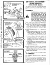
STORAGE
Remove
mower
from
tractor
for
winter
storage. When
mowe
r
is
to
be
stored
for
a period
of
time,
clean
it
thoroughly,
re·
move a
ll
dirt,
grease, leaves,
etc.
Give blades
and
und~'rside
of
housing a
good
coat
of
grease
or
rust preventative.
Store
in a
clean
dry
area.
Ea
ch
mand
r
el
should
be filled
with
grease
thru
the
Grease
Fitting
located
between
mower
blade
and
underside
of
the
mower
housing (Fig.
21
). Wipe fitting clean
before
greasin!l
Use
high pe
rform
ance
extreme
pressure lubricating grease,
(Amdex No. 1 EP
or
equ
iv
alent). Add grease until it oozes
OL
•t
around
the
cap
above
the
blade
and
under
the
sheave.
Thi
s
will
not
damage
the
grease retainer. Wipe mandrel clean
of
e::·
cess grease. This grease
may
be
obtained
by
ordenng
thr.,
your
nearest Sears repair parts d
epar
tment.
Part
No.
255711
Sears.
Roebuck
and
Co.
or
Simpsons-Sears Ltd. in
Cana<l!'l
,.
serves
the
right
to
make
any changes
in
design
or
irurr<'v•.
ments
w
ith
out
imposing
any
obligation
to
install
the
s,rr:·~
.g.
upon
its items
heretofore
manufactured.
another free manual from www.searstractormanuals.com