


................................... ,.................. .........................????_,.. .......
I It
i i i ,, ,
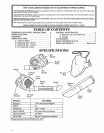
ASSEMBLY
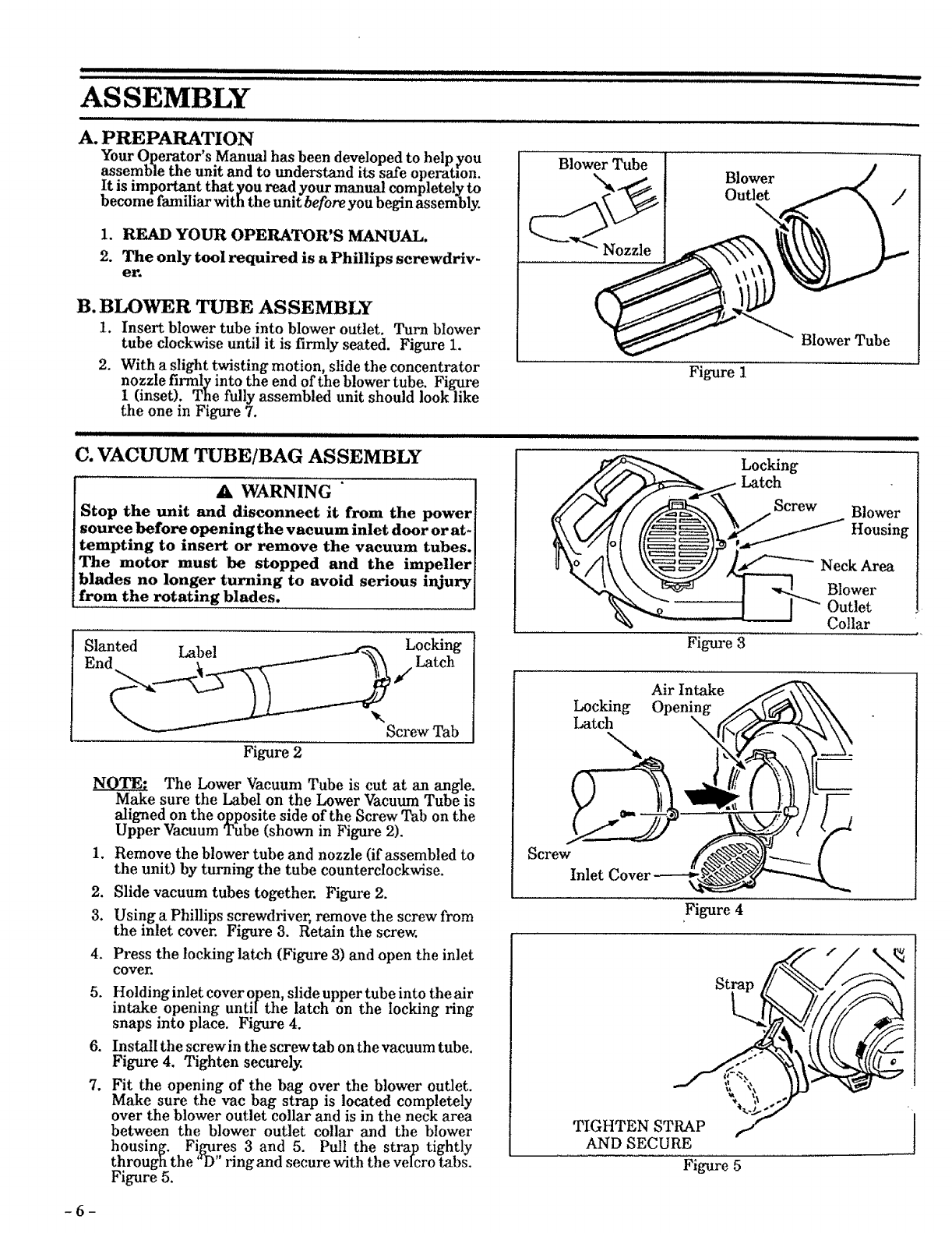
A. PREPARATION
_5
our Qperator s Manual has been developed to help you
assemble the unit and to understand its safe operation.
It is important that you read your manual completely to
become familiar with the unit before you begin assembly.
1. READ YOUR OPERATOR'S MANUAL.
2. The only tool required is a Phillips screwdriv-
er.
B. BLOWER TUBE ASSEMBLY
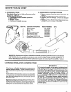
1. Insert blower tube into blower outlet. Turn blower
tube clockwise until it is firmly seated. Figure 1.
2. With a slight twisting motion, slide the concentrator
nozzle firmly into the end of the blower tube. Figure
I (inset). The fully assembled unit should look like
the one in Figure 7.
II]WII IIIII IIIIIIIII II]llJ II IIIIIIIII II IIIIIIIJl ] IIII
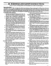
C. VACUUM TUBE/BAG ASSEMBLY
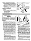
A WARNING
Stop the unit and disconnect it from the power
source before opening the vacuum inlet door or at-
tempting to insert or remove the vacuum tubes.
The motor must be stopped and the impeller
blades no longer turning to avoid serious injury
from the rotating blades.
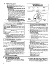
Slanted Label Locking
End _ _/Latch
Figure 2
Screw Tab
The Lower Vacuum Tube is cut at an a_gle.
Make sure the Label on the Lower Vacuum Tube is
aligned on the opposite side of the Screw Tab on the
Upper Vacuum Tube (shown in Figure 2).
1. Remove the blower tube and nozzle (if assembled to
the unit) by turning the tube counterclockwise.
2. Slide vacuum tubes together. Figure 2.
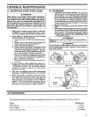
3. Using a Phillips screwdriver, remove the screw from
the inlet cover. Figure 3. Retain the screw.
4. Press the locking latch (Figure 3) and open the inlet
cover.
5. Holding inlet cover open, slide upper tube into the air
intake opening untiIthe latch on the locking ring
snaps into place. Figure 4.
6. Install the screw in the screw tab on the vacuum tube.
Figure 4. Tighten securely.
7. Fit the opening of the bag over the blower outlet.
Make sure the vac bag strap is located completely
over the blower outlet collar and is in the neck area
between the blower outlet collar and the blower
housing. Figures 3 and 5. Pull the strap tightly
through the "D' ringand secure with the veIcro tabs.
Figure 5.
Blower Tube
Blower
Outlet
Figure 1
Btower Tube
]ll]]lllllllllllllIIIllIIIIIII II II Illllllll II II IIII ]]IU
Locking
Latch
%
Figure 3
Air Intake
Figure 4
Locking
Latch
Screw
Blower
Housing
Neck Area
Blower
Outlet
Collar
Screw
Inlet
TIGHTEN STRAP
AND SECURE
Figure 5
J
-6-