


changeinskincolorortexture,orloss
offeelinginthefingers,hands,or
joints,discontinuetheuseofthistool
andseekmedicalattention.Ananti-
vibrationsystemdoesnotguarantee
theavoidanceoftheseproblems.
Userswhooperatepowertoolsona
continualandregularbasismustmoni-
torcloselytheirphysicalconditionand
theconditionofthistool.
SAVE THESE INSTRUCTIONS
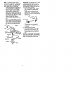
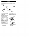
CARTON CONTENTS
Check carton contents against the fol-
lowing list.
Model 358.792442
• Brushcutter attachment
• Handlebar
• Handlebar mounting bracket for 1"
(2.5 cm) shaft
• Handlebar mounting bracket for 7/8"
(2.2 cm) shaft
• Bracket cover (2)
• Shoulder strap
• Upper shoulder strap clamp
• Lower shoulder strap clamp (with
spacer tabs)
• Handlebar bracket screws (4)
• Shoulder strap clamp screws (2)
• 4-point weed blade (assembled on
brushcutter attachment)
• Large nut for installing blade
• Retaining washer
• Cupped washer
• Metal shield (assembled on brush-
cutter attachment)
• Trimmer head
• Plastic shield
• Wing nut (screwed onto plastic shield)
• Attachment Hanger
• Hex Wrench
• Container of line
Examine parts for damage. Do not use
damaged parts.
NOTE: If you need assistance or find
that parts are missing or damaged, call
1-800-235-5878.
ASSEMBLY
zt _
4I_WARNING: If received assembled,
repeat all steps to ensure your unit is
properly assembled and all fasteners
are secure.
• A hex wrench (provided) is required
for assembly.
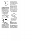
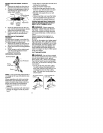
INSTALLING BRUSHCUTTER AT-
TACHMENT
CAUTION: When removing or instal-
ling attachments, place the unit on a
flat surface for stability.
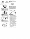
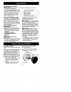
1. Loosen the coupler by turning the
knob counterclockwise.
Coupler
LOOSEN
TIGHTEN Knob
2. Remove the shaft cap from the
brushcutter attachment (if present).
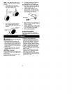
3. Position locking/release button of
attachment into guide recess of
coupler.
4. Push the attachment into the cou-
pler until the locking/release button
snaps into the primary hole.
5. Before using the unit, tighten the
knob securely by turning clock-
wise.
Coupler Primary Hole
\ /_uide Recess
UPPa_r Release ALa°c_emr nt
S ft Button t c e
£A _
aWARNING: Make sure the lock-
ing/release button is locked in the pri-
mary hole and the knob is securely
tightened before operating the unit.
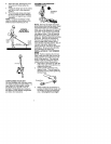
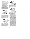
HANDLEBAR ASSEMBLY
DANGER: RISK OF CUT. To avoid
serious injury, the barrier portion of the
handlebar must be installed as shown
on the upper shaft of the powerheed to
provide a barrier between operator and
the spinning blade. Attach handlebar
mounting bracket above arrow on
safety warning decal on the upper
shaft powerhead end of unit). Ensure
hand ebar s post oned on mount ng
bracket at the end of the arrow on the
handlebar decal.