


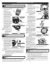
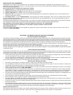


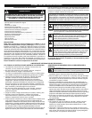
3. Fully press and
release the primer
bulb 10 times, slowly.
Some amount of fuel
should be visible in
the primer bulb and
fuel lines (Fig. 11). If
you can’t see fuel in
the bulb, press and
release the bulb as
many times as it
takes before you can
see fuel in it.
4. Place the choke lever
in Position 1 (Fig. 11).
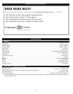
5. Crouch in the starting
position (Fig. 12).
Press the throttle
lockout in and fully
squeeze the throttle
control lever. Pull the
starter rope 5 times.
6. Place the choke lever
in Position 2 (Fig. 11).
7. While pressing the throttle lockout in and squeezing the
throttle control , pull the starter rope 1 to 4 times to start
the engine.
8. Keep the throttle squeezed and allow the engine to warm
up for 15 to 30 seconds.
9. Place the choke lever in Position 3 (Fig. 11). The unit is
ready for use.
IF...
The engine does not start, go back to step 3.
IF...
The engine fails to start after a few attempts, place the
choke lever in Position 3, press the throttle lockout in
and squeeze the throttle control. Pull the starter rope 3 to
8 times. The engine should start. If not, repeat.
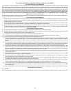
STOPPING INSTRUCTIONS
1. Release your hand from the throttle control. Allow the
engine to cool down by idling.
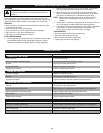
2. Press and hold On/Off Stop Control in the OFF (O) position
until engine comes to a complete stop (Fig. 10).
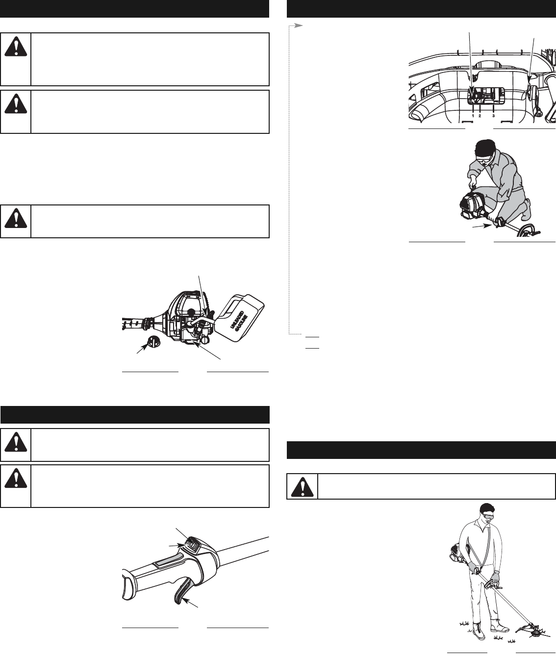
OPERATING INSTRUCTIONS
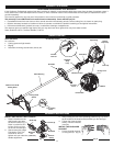
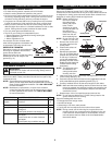
HOLDING THE TRIMMER
Before operating the unit, stand in the
operating position (Fig. 13). Check for
the following:
• The operator is wearing eye
protection and proper clothing
• With a slightly-bent right arm, the
operator’s right hand is holding the
shaft grip
• The operator’s left arm is straight, the
left hand holding the handle
• The unit is at waist level
• The cutting attachment is parallel to
the ground and easily contacts the
grass without the need to bend over
WARNING:
Always wear eye, hearing, foot and body
protection to reduce the risk of injury when operating this unit.
Fig. 13
6
OIL & FUEL INFORMATION
Using Fuel Additives
The use of fuel additives, such as STA-BIL® Gas Stabilizer or an
equivalent, will inhibit corrosion and minimize the formation of gum
deposits. Using a fuel additive can keep fuel from forming harmful
deposits in the carburetor for up to six (6) months. Add 0.8 oz. (23 ml.) of
fuel additive per gallon of fuel according to the instructions on the fuel
additive container. NEVER add fuel additives directly to the unit's gas tank.
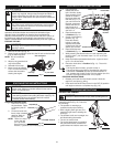
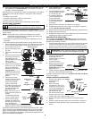
FUELING THE UNIT
1. Remove the fuel cap (Fig. 9).
2. Place the gas container’s spout into the fill hole on the fuel tank
(Fig. 9) and fill the tank.
NOTE: Do not overfill the
tank.
3. Wipe up any gasoline that
may have spilled.
4. Reinstall the fuel cap.
5. Move the unit at least 30
ft. (9.1 m) from the fueling
source and site before
starting the engine.
WARNING:
Gasoline is extremely flammable. Ignited
vapors may explode. Always stop the engine and allow it
to cool before filling the fuel tank. Do not smoke while
filling the tank. Keep sparks and open flames at a distance
from the area.
WARNING:
Add fuel in a clean, well ventilated outdoor
area. Wipe up any spilled fuel immediately. Avoid creating
a source of ignition for spilt fuel. Do not start the engine
until fuel vapors dissipate.
Fuel Cap
Fuel Tank
Fig. 9
WARNING:
Remove fuel cap slowly to avoid injury from
fuel spray. Never operate the unit without the fuel cap
securely in place.
Gas Can Spout
STARTING INSTRUCTIONS
STARTING/STOPPING INSTRUCTIONS
WARNING:
Operate this unit only in a well-ventilated
outdoor area. Carbon monoxide exhaust fumes can be
lethal in a confined area.
WARNING:
Avoid accidental starting. Make sure you are
in the starting position when pulling the starter rope (Fig. 12).
To avoid serious injury, the operator and unit must be
in a stable position while starting.
1. Check the oil level in
the crankcase. Refer
to Checking the Oil
Level.
2. Fill the fuel tank with
fresh, clean unleaded
gasoline. Refer to
Fueling the Unit.
NOTE: There is no need
to turn the unit
on. The On/Off
Stop Control is in
the ON ( I ) position at all times (Fig. 10).
Start/On ( I )
Stop/Off (O)
Throttle Control
Fig. 10
Starting
Position
Throttle Control
Fig. 12
Primer Bulb
Fig. 11
STARTING/STOPPING INSTRUCTIONS
Choke Lever