


17 - English
MAINTENANCE
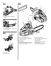
REPLACING BAR AND CHAIN
See Figures 24 - 28.
WARNING: Remove the battery pack from
the chain saw and make sure the chain has
stopped before you do any work or making
any adjustments on the saw. Failure to do so
may result in accidental starting and possible
serious injury.
WARNING: The safety instructions in this
section are to protect the user from serious
personal injury.
WARNING: Always wear gloves when han-
dling the bar and chain; these components are
sharp and may contain burrs.
WARNING: Never touch or adjust the chain
while the motor is running. The saw chain is
very sharp; always wear protective gloves when
performing maintenance to the chain to avoid
possible serious lacerations.
Remove the battery pack before you do any
work on the chain saw.
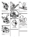
Remove the hex key from the storage area
and use it to remove the chain cover screw,
washer and chain cover from the chain saw.
Remove the bar and chain from the mounting
surface.
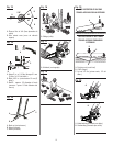
Remove the old chain from the bar.
Lay out the new saw chain in a loop and
straighten any kinks. The cutters should face
in the direction of chain rotation. If they face
the opposite direction, turn the loop over.
Place the chain drive links into the bar groove.
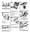
Position the chain so there is a loop at the
back of the bar. Hold the chain in position on
the bar and place the loop around the sprock-
et of the chain saw. Fit the bar flush against
the mounting surface so that the bar stud is in
the long slot of the bar.
NOTE: When placing the bar on the bar stud,
assure that the adjusting pin is in the chain
tension pin hole.
RECOMMENDED BAR AND CHAIN
COMBINATIONS
Bar Part Number - 10 in.
671834006
Chain Part Number
6958301 or 690583002
Replace the chain cover, washer and chain
cover screw. Tighten the chain cover screw
finger tight only. The bar must be free to
move for tension adjustment.
Remove all the slack from the chain by turn-
ing the chain tensioning screw clockwise until
the chain seats snugly against the bar with
the drive links in the bar groove.
Lift the tip of the guide bar up to check for
sag. Release the tip of the guide bar and turn
the chain tensioning screw 1/2 turn clock-
wise. Repeat this process until sag does not
exist.
Hold the tip of the guide bar up and tighten
the bar mounting screw securely.
Chain is correctly tensioned when there is no
sag on the underside of the guide bar, the
chain is snug, but it can be turned by hand
without binding.
NOTE: If chain is too tight, it will not rotate.
Loosen the chain cover screw slightly and
turn tension adjuster 1/4 turn counterclock-
wise. Lift the tip of the guide bar up and
retighten chain cover screw securely. Assure
that the chain will rotate without binding.
Place the hex key back into the storage area.
CHAIN TENSION
See Figures 29 - 30.
Stop the motor before setting the chain ten-
sion. Make sure the guide bar screw is loos-
ened to finger tight, turn the chain tensioner
clockwise to tension the chain. Refer to Re-
placing Bar and Chain earlier in this manual
for additional information.
A cold chain is correctly tensioned when there
is no slack on the underside of the guide bar,
the chain is snug, but it can be turned by
hand without binding.
Chain must be re-tensioned whenever the
flats on the drive links hang out of the bar
groove.