


23
• Reinstall the belt cover on front of the engine
with the two self-tapping screws and flat
washers.
• Reattach the chute crank to the chute assembly
with the hairpin clip and flat washer.
NOTE: Make sure that the auger cable is routed in
front of the belt.
Drive Belt
• Check drive belt every 50 hours of operation for
wear and tear.
• Drain the gasoline from the snow thrower, or
place a piece of plastic under the gas cap.
• Remove the plastic belt cover on the front of the
engine by removing the two self-tapping screws.
• Tip the snow thrower up and forward, so that it
rests on the housing.
• Remove six self-tapping screws from frame cover
underneath the snow thrower.
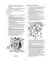
• Pull the idler pulley away from the drive belt and
remove the belt from the engine pulley. You will
find the idler pulley in front of the engine and
under the belt cover that you removed earlier.
See Figure 27.
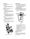
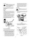
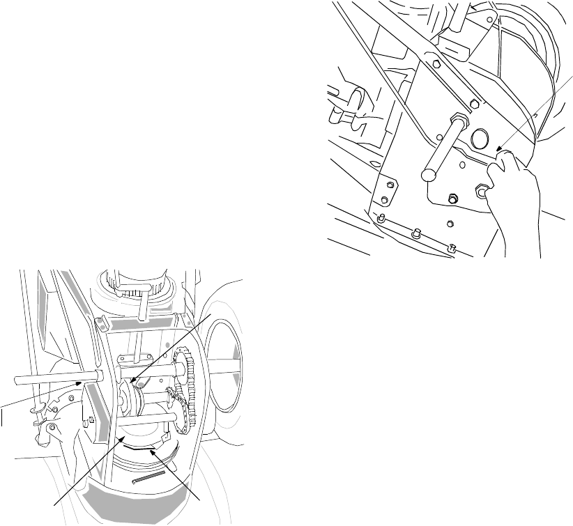
• Working from the underside of the frame, slip
belt between the friction wheel and the friction
wheel disc. See Figure 30. You may have to
twist the belt flat in order to slide it through the
clearance between the friction wheel and the
friction wheel disc. Remove the belt.
• Install new belt. Reassemble following the
instructions in reverse order.
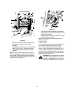
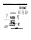
Figure 30
Friction
Wheel
Drive Belt
Location
Friction
Wheel
Disc
Idler
Pulley
Location
Changing Friction Wheel Rubber
• Check the rubber on the friction wheel after 25
hours of operation, and periodically thereafter.
Replace the rubber if any signs of wear or
cracking are found.
• Drain the gasoline from the snow thrower, or
place a piece of plastic under the gas cap.
• Tip the snow thrower up and forward, so that it
rests on the housing.
• Remove six screws from the frame cover
underneath the snow thrower.
• Remove klick pin securing the left wheel, and
remove the wheel from the axle.
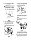
• Remove the four screws securing the left drive
cover to the frame. Remove the drive cover from
the side of the frame. See Figure 31.
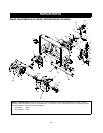
Figure 31
• Holding the friction wheel assembly, slide the
hex shaft out of the left side of the unit. The
spacer on the right side of the hex shaft will fall
and the sprocket should remain hanging lose in
the chain.
• Lift the friction wheel assembly out between the
axle shaft and the drive shaft assemblies.
• Remove the six screws from both sides of the
friction wheel assembly. Remove friction wheel
rubber from between the friction wheel plate.
• Reassemble new friction wheel rubber to the
friction wheel assembly, tightening the six
screws in rotation and with equal force. It is
important to assemble the rubber on the friction
wheel equally for proper functioning.
• Insert the pin from the shift arm assembly into
the friction wheel assembly and hold assembly
in position. See Figure 32.
Drive
Cover