


17
SERVICE AND MAINTENANCE
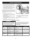
Drive Control
Refer to the Adjustment section of the Assembly instructions to adjust
the drive control. To further check the adjustment, proceed as follows:
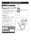
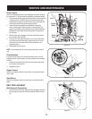
With the snow thrower tipped forward (be certain to drain gasoline
or place plastic film under the gas cap if the snow thrower has
already been operated), remove the frame cover underneath the
snow thrower by removing the self-tapping screws.
Locate the opening between the axle support bracket and
the front frame support (See Figure 20). Looking through this
opening, with the drive control released, there must be clearance
between the friction wheel and the drive plate in all positions of
the shift lever.
With the drive control engaged, the friction wheel must contact
the drive plate. See Figure 20.
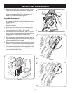
If there is no friction wheel clearance, or the friction wheel does
not solidly contact the drive plate, re-adjust the lock nut on the
lower end of the drive cable following the instructions in the
Assembly section.
Reassemble the frame cover.
NOTE: If you placed plastic film under the gas cap earlier, remove it
now.
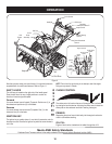
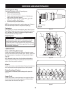
Chute Bracket
If the spiral at the bottom of the chute directional control is not fully
engaging with the chute assembly, the chute bracket can be adjusted.
To do so:
Loosen the two nuts which secure the chute bracket and reposi-
tion it slightly. See Figure 21.
Retighten the nuts.
Auger Control
Refer to the Assembly section for instructions on adjusting the auger
control cable.
Skid Shoes
Refer to the Assembly section for instructions on adjusting the skid
shoes.
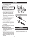
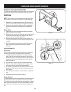
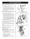
BELT REPLACEMENT
Belt Removal Preparation
Disconnect the chute crank assembly at the discharge chute end
by removing the hairpin clip and the flat washer. Refer to Figure
22.
1.
2.
3.
4.
5.
1.
2.
1.
Figure 20
Figure 21
Figure 22
Axle Supp.
Brkt.
Opening
Drive
Plate
Friction
Wheel