


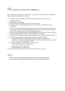
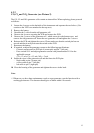

4.2.2
CO, Cl
2
and NO
2
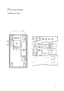
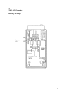
Generator (see Picture 2)
The CO, Cl
2
and NO
2
generator cells contain an internal fan. When replacing, please proceed
as follows:
1 Loosen the 4 screws on the backside of the instrument and seperate the two halves. (Use
caution as the LED’s are attached to the top case)
2 Remove the battery.
3 Unsolder the 3 wires from the old generator cell.
4 Unscrew the 4 screws securing the PCB and remove the PCB.
5 Unscrew the 3 screws of the generator cell , which secure it to the bottom case, and
remove the old generator cell. Insert the new generator cell and tighten the 3 screws.
6 Reinsert the PCB and tighten the screws. Please make sure that the switch pin has not
moved and that it easily activates the switch on the PCB.
7 Reconnect the battery.
8 If required, readjust the generator current to the following specifications:
- Connect current meter to PCB pin 4 (center pin) and pin 7 (left pin).
- Press switch S101 and adjust generator current with potentiometer R114 to the
applicable current:
CO = 13 mA; Cl
2
= 0,3 mA; NO
2
= 5 mA
9 Solder the wires of the generator cell and the fan to the PCB pins:
- black cable to pin 4 (center pin)
- yellow cable to pin 7 (left pin)
- red cable to pin 3 (right pin)
10 Close the housing of the generator and tighten the screws in the back.
Note:
) Whenever you have done maintenance work on a gas generator, test the function with a
working gas detector. The detector should give an alarm within 10 seconds.
12