


6
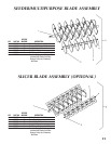
OPTIONAL BLADE
ASSEMBLIES
CHANGING BLADE ASSEMBLIES
Within minutes your machine can be converted to
a turf rake, turf seeder or turf slicer by purchasing
the optional blade assemblies available complete
with side plates, bearings and drive pulley.
Changing the blade assembly can be done quickly
as described below.
1. Set unit up on block allowing enough
distance beneath machine to change
blade assembly.
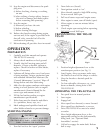
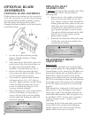
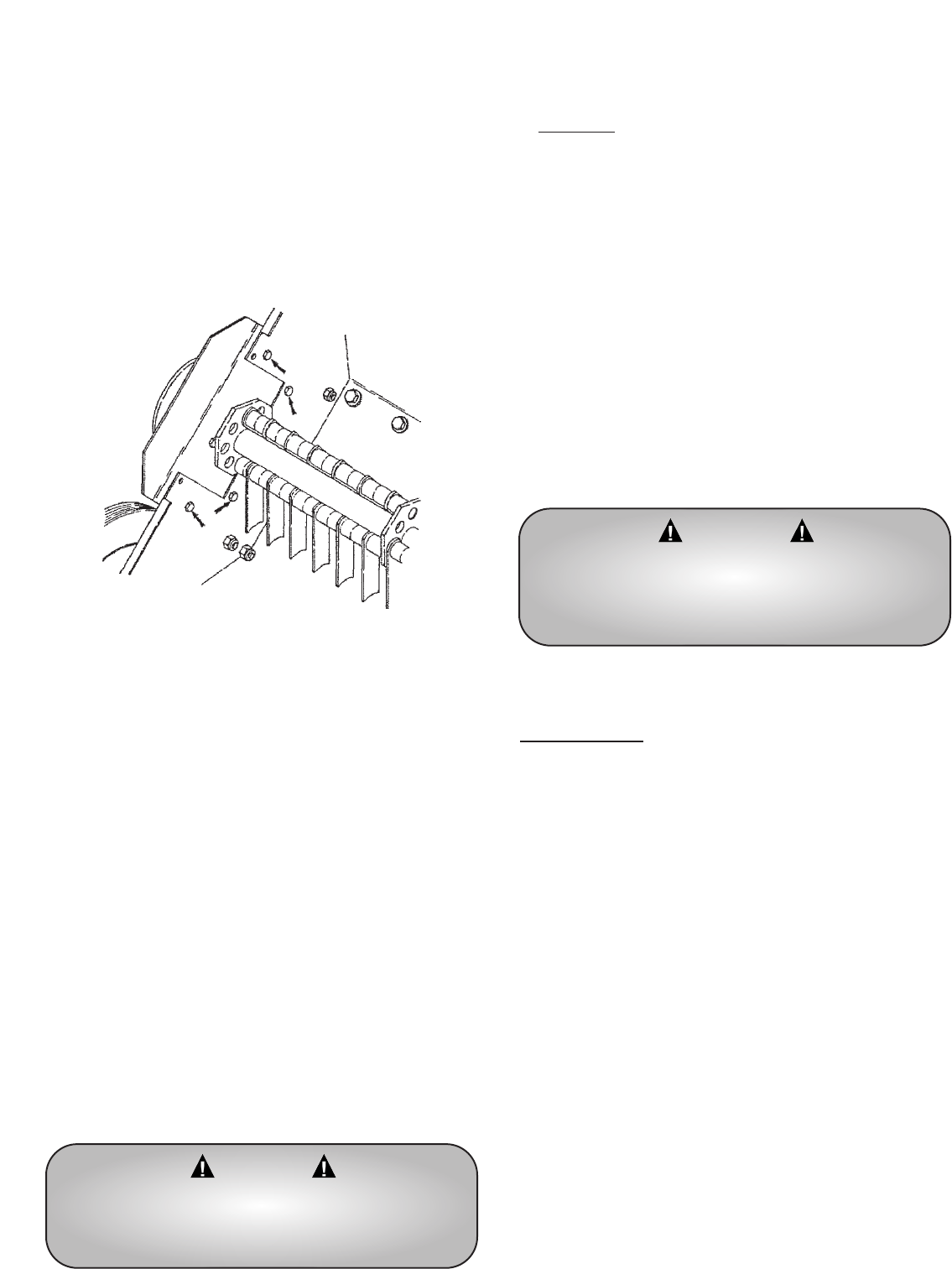
2. After removing the belt shield, remove the
twelve bolts on the left side and three on
the right side which hold the blade
assembly to the main body (see Fig. 3).
3. Remove the belts from both sides and
remove the entire blade assembly. There is
no need to loosen any set screws.
4. Next install the optional blade assembly
and fasten with six 1/4” x 5/8” bolts on
each side. Tighten all bolts on both shields.
Center the shaft and tighten the two set
screws in each bearing using Pro Lock
(nut type, medium strength).
5. When changing back to the original shaft it
will not be necessary to loosen any set
screws. Only the bolts in the belt shields
and the eight bolts holding the shaft will
need to be removed.
CAUTION
BE CERTAIN THAT THE SET SCREWS ARE
TIGHTENED PROPERLY IN BEARINGS AND PULLEY
WHEN REASSEMBLING.
REPLACING SHAFT
ASSEMBLY ONLY
If replacing the existing shaft assembly, only follow
steps 1 through 3 above. Proceed with the
following steps.
1. Remove the two drive pulleys and bearing
plates from the main shaft (one on each
side). Replace with new shaft. Reinstall the
bearing plates and drive pulleys on the new
shaft using Pro Lock (retaining 1, medium
strength) on the shaft and Pro Lock (nut
type, medium strength) on the set screws.
The pulleys will be positioned on the shaft
by bolts, the 1/4” lock washer and the
pulley retainer washer.
2. Route the belt behind the idler pulleys and
roll the belts onto the lower pulleys then
reinstall the belt shields.
RECOMMENDED HEIGHT
ADJUSTMENTS
Raking Height
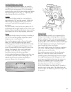
When using the Turf Rake with its raking (flail)
blade assembly adjust the raking height as follows.
Normal height is set by placing the Turf Rake on a
hard surface making sure one satellite shaft is at
dead bottom. Adjust the wheels so the raking
fingers on the bottom shaft just touch the ground.
DO NOT set the fingers so that they will penetrate
the ground as this will counteract the centrifugal
force of the fingers and prevent the from raking
properly.
With repeated use, raking side of the fingers will
begin to wear. To give the fingers a new square
raking edge, remove the end plates and turn the
entire main shaft assembly 180° and replace it on
the Turf Rake. NOTE: Use Pro-Lock (retaining 1,
medium strength) on the 7” pulley on the
main shaft.
To prolong the life of the main shaft, extra holes
are provided. If the circular holes holding the
satellite shafts become distorted, rotate all four
satellite shafts to the next set of holes.
WARNING
CAUTION: BE CERTAIN THAT THE SET SCREWS
ARE TIGHTENED PROPERLY IN BEARINGS AND
PULLEY WHEN REASSEMBLING.
Fig. 3