29
SET POINTS
This instrument allows to use 2 set points: SP and
SP2.
The set point selection is possible only by logic
input.
Set point transfer:
The transfer between one set point to another (or
between two different set point values) may be
realized by a step transfer or by a ramp with two
different programmable rate of change (ramp up
and ramp down).
Slope value: 1 - 100 eng. unit/min or step.
Set points limiter: RLO and RHI parameters, pro-
grammable.
CONTROL ACTIONS
Control action: PID + SMART
Type: One (heating or cooling) or two (heating and
cooling) control outputs.
Proportional Band (Pb):
Range: - from 1.0 to 100.0 % of the input span for
process with one control output.
- from 1.5 to 100.0 % of the input span for
process with two control outputs.
When Pb=0, the control action becomes ON/OFF.
Hysteresis (for ON/OFF control action):
from 0.1% to 10.0% of the input span.
Integral time (Ti): from 1s to 20 min. or excluded.
Derivative time (Td): from 1 s to 10 min.
If zero value is selected, the derivative action is
excluded.
Integral pre-load:
- from 0.0 to 100.0 % for one control output
- from -100.0 (cooling) to +100.0 % (heating) for
two control outputs.
SMART: keyboard enabling/disabling
Auto/Manual: selectable by front pushbutton.
Auto/Manual transfer: bumpless method type
Indicator "MAN" : OFF in auto mode and lit in
manual mode.
OUTPUTS
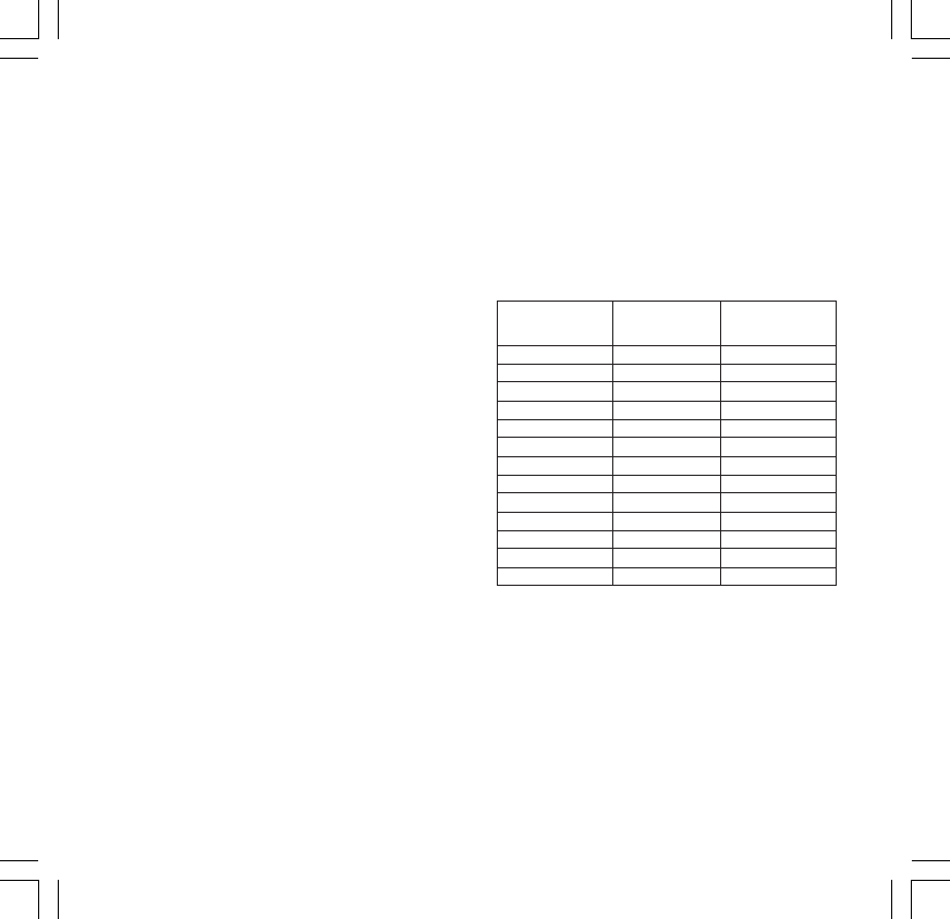
Type: This instrument is equipped with 3
independent outputs programmable as follows:
Out 1 Out 2 Out 3
linear (mA) relay relay
Heating AL1 AL2
Heating Cooling AL2
Heating AL1 Cooling
Cooling AL1 AL2
Cooling Heating AL2
Cooling AL1 Heating
Retransm. Heating AL2
Retransm. AL1 Heating
Retransm. Cooling AL2
Retransm. AL1 Cooling
Retransm. Heating Cooling
Retransm. Cooling Heating
Retransm. AL1 AL2
Control output updating time :
- 250 ms when a linear input is selected
- 500 ms when a TC or RTD input is selected.
Action: direct/reverse programmable by front
keyboard.
Output level indication:
The instrument displays separately the output 1
level (heating) and the output 2 level (cooling).
Output status indication: the OUT 1 LED will
flash with a duty cycle proportional to the output 1
power. Two indicators (OUT 2 and/or OUT 3) are
lit when the respective output is in ON condition.
1604-7-1-AB.p65 5/16/00, 10:50 AM29


