


Page 7For technical questions, please call 1-800-444-3353.SKU 90599
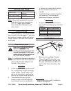
permanently mounting the Solar
panels on a rooftop.
7.
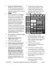
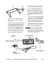
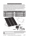
Solar Panels (1)
Regulator (2)
lead
wires
Hook-Up Diagram
Connect the two ring connectors at
the end of the lead wires coming
from the Solar Panels (1) to the
Solar Terminals on the Regulator
(2). See FIGURE 1. Be sure to
connect by matching polarities on
the wires and the Regulator (2).
Black (-) is negative and red (+) is
positive. Then, connect the wire
leads so that all of the Solar Panels
(1) are connected to each other and
the Regulator (2) (again, making
sure you are hooking up to the right
polarity on the Regulator). See
Hook-Up Diagram, above.
Wiring
Note: Only a licensed electrician and
a licensed building contractor can
safely design and implement a grid
tie-in system. Any grid tie-in system
must meet all applicable building
and electrical codes, and must meet
standards established by the area
power company.
1. Run wires from the panels, through
weatherproof grommets and into
the enclosure where the charge
controller/regulator is located. Use
wires of the proper size and rating.
2. Connect to charge controller/regulator
according to controller/regulator’s
instructions.
3. Secure all connections using
terminals, or solder all wire splices to
ensure good connections.
4. Weatherproof all connections.
OPERATION
Note: Performance of the Solar Panels
will vary dependent on site location,
angle of the panels in relation to the
arc of the sun, and available sunlight.
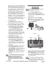
Recharging a Battery
1. To recharge a 12 volt battery (not
included), while paying attention
to the proper polarity (black (-) is
negative and red (+) is positive),
connect the two ring terminals on
the Battery Connector (3) to the
Battery Terminals on the back of
the Regulator (2). See FIGURE
1. Then, connect the black clamp to
the black or negative (-) terminal on
the battery (not included). Finally,
connect the red clamp to the red or
positive (+) terminal on the battery.
Avoid accidental contact of the red
and black battery clamps to each
other.
Note: Do not change the order explained
in number 1 above or electric shock
resulting in serious injury or death
may occur.
2. Turn on the Regulator. See the On/
Off switch in FIGURE 1 on page 6.
3. Never leave the battery (not included)
unattended while charging. When
the battery (not included) is fully
charged, the reading on the voltage
display will show “13” or above.
Note: the voltage display will have to
be turned on in order to monitor the