


Introduction
Congratulations on the purchase of your new CHAUVET lighting control system. We are confident you
will enjoy many trouble free hours with this unit. To assist with the care and use of the product we have
prepared this short guide.
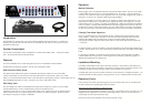
System Components
The SF-9005 Control System comes complete with 1- Multi-Function Switch Panel, 1- Relay Pack (SR-8)
and 1- 25 foot 9-pin Extension Cable (SF-
EXCB).
Features
This unit is switchable and has been designed to operate on 120V-50/60Hz or 230V-50/60Hz.
SF-9005 offers two modes of operation: manual, and chasing timer control.
Multi-Function Switch Panel-
The ‘Multi-Function Switch Panel’ features 8 individual “on/off/chase” switches, 2 “timer speed dials”,
“strobe” control button (for use with all mono strobes) with features of all on/speed control, “fog” control
button ( for use with FX-800/F-1050/F-1250/F-1700) with feature of operating fog machine, “control switch” (for use
with CH-865/866) with feature of “all on”, “blackout”, and “chase”, and master “on/off”.
SR-8 Relay Pack-
The ‘SR-8 Relay Pack’ features 8 switched power sockets (that correspond to channel 1-8 on the ‘Multi-
Function Switch Panel’, and one unswitched power socket for constant on item).
2 SR-8 relay packs may be run off one multi-function switch panel. Simply connect an SF-EXCB extension
cable from the “line out” on one SR-8 relay pack to the “line in” on another relay pack. Please note maxi-
mum load per relay pack is 15amps or 1800watts.
Operation
Manual Operation-
Before plugging unit in, the EXCB-25 extension cable must be linked from the “line out” on the ‘Multi-
Function Switch Panel’ to the “line in” on the SR-8 Relay Pack. To connect, gently push the 9-pin
connector on the extension cable into the appropriate “line” and screw down snugly the two screws on
either side. For longer runs, extension cables may be linked together.
Turn all channel switches and master switch to “off” position on ‘Multi-Function Switch Panel’. Plug
switch panel and relay pack in. Plug items into the appropriate socket on the relay pack. Turn the
master switch to the “on” position. The switch should illuminate. Switch the desired channel switches
to the “on” position. Channel switch will illuminate and the item plugged into the socket for that chan-
nel will begin to operate. With channel switch in the “off” position depress and release “flash buttons”
for quick on and off. (Note: item will remain operational for as long as the flash button is depressed).
Chasing Timer Mode Operation-
Set up as described above in manual Operation Section. Switch desired channel switches to the
“chase” position. In timer mode, each bank of four channels chases separately within each bank.
Indicator lights will illuminate to indicate chase. Features 16 built-in patterns that operate in
manual/sound activation. Adjust the “timer speed dials” for each band to adjust chases speed from
1-13 minutes.
For strobe operation, connect EST-10Mono cable (sold separately) from “Multi-Function Switch Panel’
to strobe. Choose options of “on” and “speed control” located on the front of the ‘Multi-Function Switch
Panel.”
For fog machine operation, connect EXT-2 Fogger Extension Cable (sold separately) from “Multi-
Function Switch Panel’ to fog machine. When fog machine is warmed up, depress “fog button” on
‘Multi-Function Switch Panel’ to disperse fog.
Installation/Mounting
The ‘Multi-Function Switch Panel’ may be used either seated on a level surface or mounted into an
appropriate 19” (2U space) rack cabinet. For reasons of safety it is best to secure the unit into a rack
or suitable mounting so that the extension cables cannot be pulled out of the panel.
The SR-8 Relay Pack may be used either mounted on a level surface or to a lighting stand/truss. It is
recommended that for safety purposes, if hanging the unit, to use a suitable clamp and safety cable.
Replacing Fuses
If the unit does not function at all when plugged in and the “circuit breaker reset” on the Relay Pack
has been reset then it is highly likely that the fuse is blown.
Unplug the unit before attempting to replace the fuse.
To replace the fuse, unscrew the “fuseholder” on the back of the ‘Switch Panel’ to reveal the fuse. It is
important that the replacement fuse is of the correct rating (3amp). Failure to use the correct fuse
could damage the unit beyond economic repair.
Place the new fuse in the fuseholder, and screw the cap back snugly.