


LED Par 64-36VW B&C User Manual 12 Rev. 4
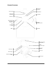
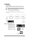
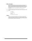
This drawing
provides a general
illustration of the
DMX input/output
panel of a lighting
fixture.
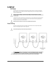
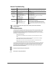
Universal DMX Controller
Continue the link
5. APPENDIX
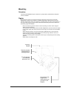
Fixture Linking
You will need a serial data link to run light shows of one or more fixtures using a DMX controller or to run
synchronized shows on two or more fixtures set to a master/slave operating mode. The combined number of
channels required by all the fixtures on a serial data link determines the number of fixtures the data link can
support.
Fixtures on a serial data link must be daisy chained in one single line. To comply with the EIA-
485 standard, no more than 32 fixtures should be connected on one data link. Connecting
more than 32 fixtures on one serial data link without the use of a DMX optically-isolated
splitter may result in deterioration of the digital DMX signal.
Maximum recommended serial data link distance: 500 m (1640 ft)
Maximum recommended number of fixtures on a serial data link: 32
Tto use this fixture in a DMX or master/slave operation, you must daisy chain, using DMX cables to link from
one fixture to another.
Setting up a DMX Serial Data Link
1. Connect the (male) 3-pin connector side of
the DMX cable to the output (female) 3-pin
connector of the controller.
2. Connect the end of the cable coming from
the controller which will have a (female)
3-pin connector to the input connector of
the next fixture consisting of a (male) 3-pin
connector.
3. Then, proceed to connect from the output
as stated above to the input of the following
fixture and so on.
Additional signal
link out